
Display panel, manufacturing method thereof and display device

A technology for display panels and array substrates, applied to semiconductor devices, electrical components, circuits, etc., can solve problems such as poor display of display panels, avoid breakage or separation from organic light-emitting layers, improve bending resistance, and improve adhesion. Effect

Active Publication Date: 2018-12-28
KUNSHAN GO VISIONOX OPTO ELECTRONICS CO LTD
View PDF4 Cites 12 Cited by
  • Summary
  • Abstract
  • Description
  • Claims
  • Application Information

AI Technical Summary

Problems solved by technology

[0005] Based on this, it is necessary to provide a display panel, its manufacturing method, and a display device that improve the above-mentioned problems in view of the problem that the display panel in the existing design is prone to poor display when it is bent and withstands a drop impact.

Method used


Image

  • Display panel, manufacturing method thereof and display device
  • Display panel, manufacturing method thereof and display device
  • Display panel, manufacturing method thereof and display device

Examples


Embodiment Construction

[0033] In order to facilitate the understanding of the present invention, the present invention will be described more fully below with reference to the associated drawings. Preferred embodiments of the invention are shown in the accompanying drawings. However, the present invention can be embodied in many different forms and is not limited to the embodiments described herein. On the contrary, these embodiments are provided to make the understanding of the disclosure of the present invention more thorough and comprehensive.

[0034] It should be noted that when an element is referred to as being “fixed” to another element, it can be directly on the other element or there can also be an intervening element. When an element is referred to as being "connected to" another element, it can be directly connected to the other element or intervening elements may also be present. The terms "vertical," "horizontal," "left," "right," and similar expressions are used herein for purposes ...


PUM


Abstract

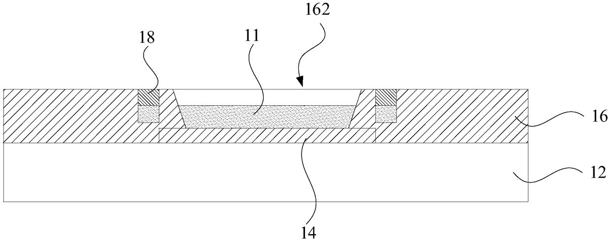
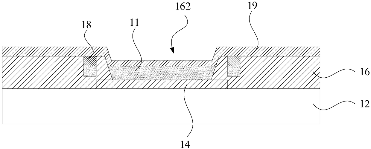
The invention relates to a display panel, comprising a pixel definition layer, a cathode and a filling structure. The cathode is overlaid on the pixel definition layer; a plurality of grooves are formed on the pixel definition layer, and the filling structure is formed of an inorganic material; the filling structure is located within the recess and is configured to contact the cathode. The pixel definition layer is provided with grooves and filled with a filling structure formed of an inorganic material. On the one hand, the grooves and the filling structure can effectively disperse stress when the display panel is impacted or bent; on the other hand, the filling structure is formed of an inorganic material, which has better adhesion with the pixel definition layer and the cathode, and theadhesion of the cathode is improved compared with the prior art design in which the cathode relies on the Van der Waals force adhesion with the pixel definition layer. As such, the fracture of the cathode or separation from the organic light emit layer is effectively avoid, and the reliability of the bending resistance and the drop impact strength of the OLED display panel is effectively improved. Also provided are a method for manufacturing a display panel and a display device.

Description

technical field [0001] The present invention relates to the field of display technology, in particular to a display panel, a manufacturing method thereof, and a display device. Background technique [0002] With the development of technologies such as big data, cloud computing, and mobile Internet, human beings have entered the era of intelligence, including smart mobile communication terminals, wearable devices, and smart home devices, which have become an indispensable part of people's work and life. As an important window for human-computer interaction in the era of intelligence, display panels are also undergoing major changes. Organic light-emitting diode (Organic Light-Emitting Diode, OLED) display panel has the advantages of thin thickness, self-luminous performance, low power consumption, and good flexibility. Flat panel display device. [0003] In order to pursue a better visual experience and tactile experience, the requirements for the effective display area and...

Claims


Application Information

Patent Timeline
Patent Type & Authority Applications(China)
IPC IPC(8): H01L27/32
CPCH10K59/00H10K59/122
Inventor 韩冰张玄甘帅燕王徐亮高峰
Owner KUNSHAN GO VISIONOX OPTO ELECTRONICS CO LTD
Learn More