
Electronic device and method of making the same using surface mount technology and an anisotropic conductive adhesive useful in the method

A technology of electronic devices and conductive adhesives, which is applied in the manufacture of printed circuits, the assembly of printed circuits with electrical components, the manufacture of semiconductors/solid-state devices, etc., and can solve problems such as non-weldable flexible parts

Inactive Publication Date: 2018-12-21
THIN FILM ELECTRONICS ASA
View PDF8 Cites 0 Cited by
  • Summary
  • Abstract
  • Description
  • Claims
  • Application Information

AI Technical Summary

Problems solved by technology

For example, in pulsed heat welding, the thermal head that applies the heat must be perfectly parallel to the part, and therefore cannot be used to weld flexible parts

Method used


Image

  • Electronic device and method of making the same using surface mount technology and an anisotropic conductive adhesive useful in the method
  • Electronic device and method of making the same using surface mount technology and an anisotropic conductive adhesive useful in the method
  • Electronic device and method of making the same using surface mount technology and an anisotropic conductive adhesive useful in the method

Examples


Embodiment Construction

[0039] Reference will now be made in detail to various embodiments of the invention, examples of which are illustrated in the accompanying drawings. While the invention will be described in conjunction with the following examples, it will be understood that these descriptions are not intended to limit the invention to these examples. On the contrary, the invention is intended to cover alternatives, modifications and equivalents, which may be included within the spirit and scope of the invention. Moreover, in the following detailed description, numerous specific details are set forth in order to provide a thorough understanding of the present invention. It will be apparent, however, to one skilled in the art that the present invention may be practiced without these specific details. In other instances, well-known methods, procedures, components, and materials have not been described in detail so as not to unnecessarily obscure relevant aspects of the present invention. In add...


PUM


Abstract

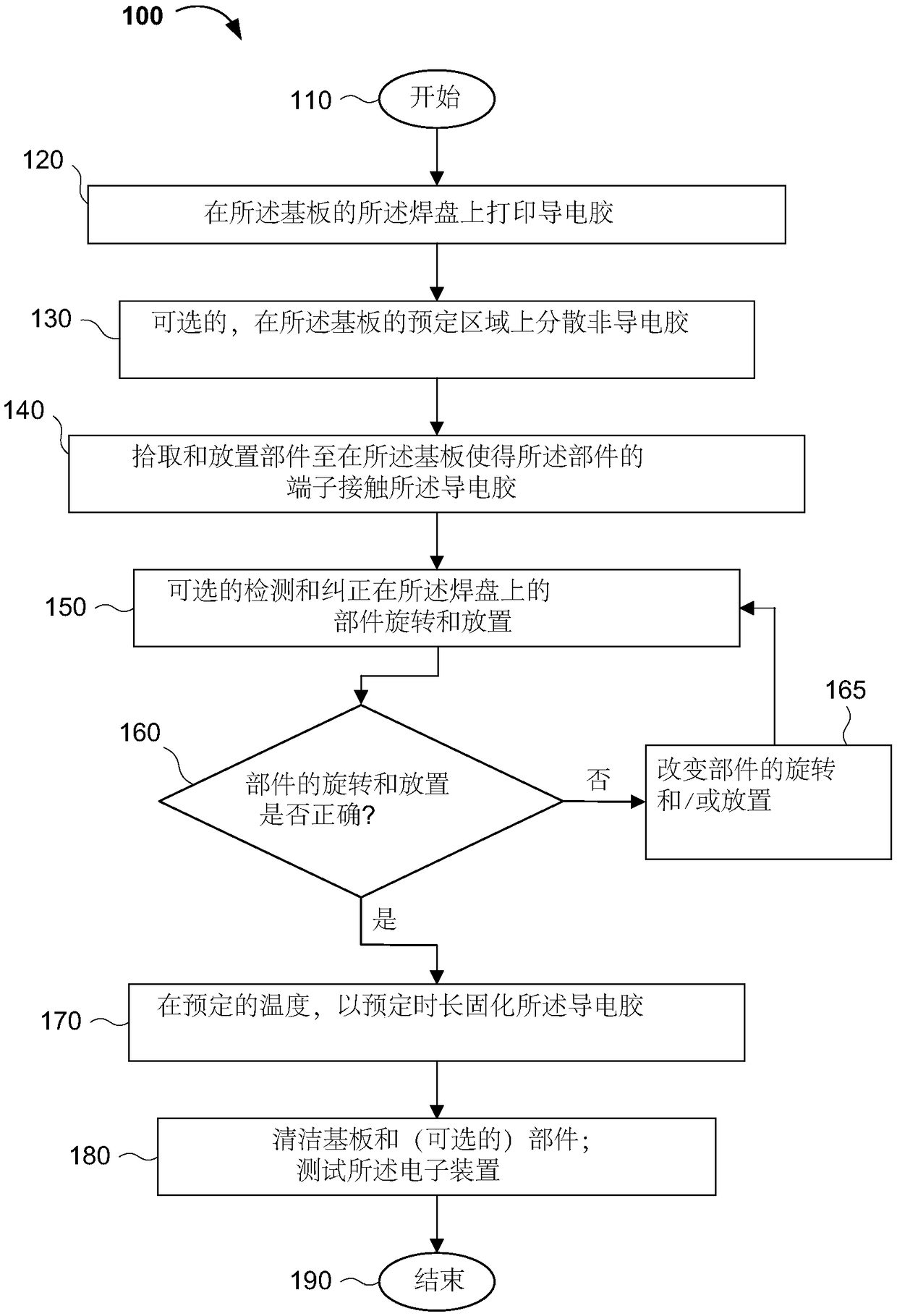
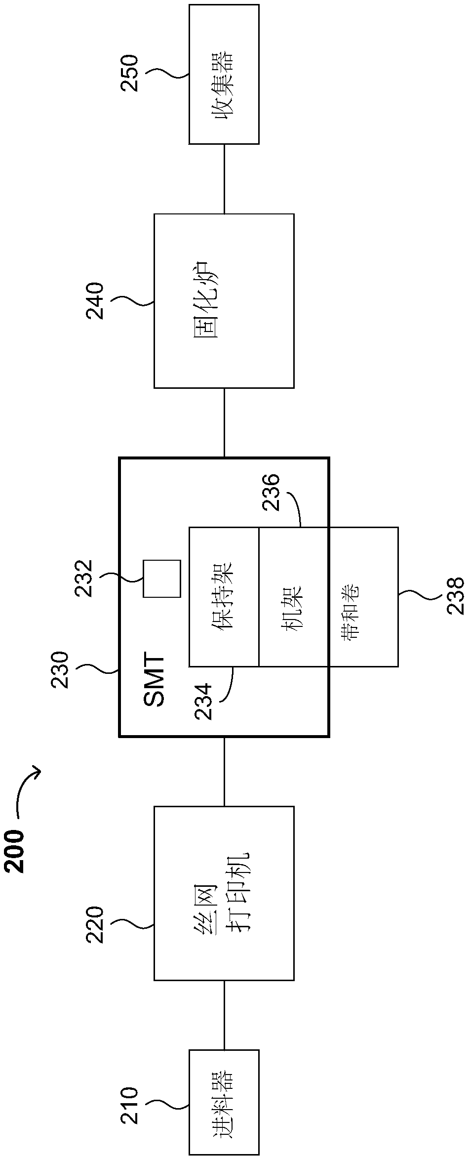
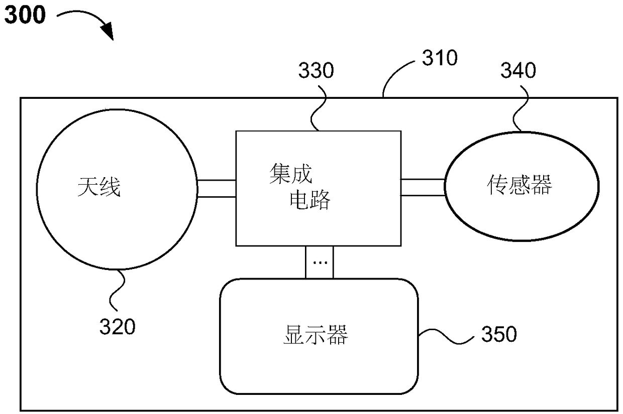
A method of and system (200) for manufacturing an electronic device (300, 300'), a curable conductive adhesive for use in the same, and an electronic device (300, 300') are disclosed. The method includes printing a conductive adhesive onto pads at ends of traces on a substrate (310, 360), placing one or more components (320, 340, 340', 350, 355) having a non-standard size and / or shape (e.g. circular, oval or rectangular with rounded corners) onto the pads with the conductive adhesive thereon, and after the component(s) (320, 340, 340', 350, 355) have been placed onto the pads, curing the conductive adhesive at a predetermined temperature or with light having a predetermined wavelength (band). The one or more components (320, 340, 340', 350, 355) having a non-standard size and / or shape maybe an antenna (320), a sensor (340, 340') and / or a display (350, 355). The electronic device (300, 300') may further comprise one or more additional components (330, 335, 370) having a standard size and / or shape on a second subset of the pads. The additional components (330, 335, 370) may be an integrated circuit (330, 335) and / or a battery (370). The system (200) comprises a printer (220) configured to print a conductive adhesive onto pads at ends of traces on a substrate, a surface mounting (SMT) machine (230) configured to place one or more components (320, 340, 340', 350, 355) having a non-standard size and / or shape onto the pads with the conductive adhesive thereon, and a curing station configured to cure the conductive adhesive after the component(s) (320, 340, 340', 350, 355) have been placed onto the pads. The SMT machine (230) may include a nozzle head having a surface with a shape identical to or configured to match a shape of the component (320, 340, 340', 350, 355) it picksup.

Description

[0001] Cross References to Related Applications [0002] This application claims the benefit of U.S. Provisional Patent Application No. 62 / 301,243, filed February 29, 2016, which is hereby incorporated by reference in its entirety. technical field [0003] The present invention generally relates to the integration and assembly of electronic devices. More specifically, embodiments of the present invention relate to electronic devices using surface mount technology and methods of manufacturing the same, and anisotropic conductive paste (ACP) useful in the methods. Background technique [0004] Components placed or mounted on circuit boards often have non-standard sizes and / or shapes. Some components may also be temperature sensitive and / or flexible. Non-standard sizes and shapes, temperature sensitivity, and flexibility can cause challenges when placing or mounting components on circuit boards using equipment designed to assemble standard components. [0005] However, meth...

Claims


Application Information

Patent Timeline
Patent Type & Authority Applications(China)
IPC IPC(8): H05K3/32H01L21/60C09J9/02H05K13/04H01L21/68H05K1/18H01L23/538H01L25/16H01L21/66H01L21/67
CPCH01L2224/83005H01L2224/75702H01L2224/2936H01L2224/29366H01L2224/2939H01L2224/83132H01L2224/75303H01L2224/29455H01L2224/29439H01L2224/29447H01L2224/75272H01L2224/29391C09J9/02H01L24/16H01L24/27H01L24/29H01L24/32H01L24/75H01L24/83H05K1/0393H05K1/189H01L2224/16227H01L2224/27312H01L2224/2732H01L2224/2919H01L2224/2929H01L2224/29339H01L2224/29347H01L2224/29355H01L2224/29387H01L2224/29499H01L2224/32227H01L2224/75611H01L2224/75651H01L2224/75745H01L2224/75753H01L2224/759H01L2224/75901H01L2224/83192H01L2224/83203H01L2224/8385H01L2224/83851H01L2224/83862H01L2224/83874H01L2224/83907H01L2924/06H01L2924/10155H01L2924/10156H01L2924/15162H05K2201/09027H05K2201/10098H05K2201/10128H05K2201/10151H01L2224/7598H01L2224/29444H01L2224/29294H01L2224/29424H01L2224/8391H01L2224/75842C09J4/00C09J5/06H05K3/323C09J2301/416H01L2924/00012H01L2924/00014H01L2924/0615H01L2924/063H01L2924/013H01L2924/05442H01L2924/05432H01L2924/0635H01L2924/0665C08F220/10H05K3/303H05K2203/168
Inventor 欧莱·哈格尔
Owner THIN FILM ELECTRONICS ASA
Learn More