Engine experiment stand and application method thereof
A test bench, engine technology, applied in the direction of engine testing, machine/structural component testing, measuring devices, etc., can solve the problem that the fixing bolts cannot be completely fixed firmly, and achieve high safety, simple structure of auxiliary equipment, The effect of reducing process steps
- Summary
- Abstract
- Description
- Claims
- Application Information
AI Technical Summary
Problems solved by technology
Method used
Image

Examples
Embodiment 1
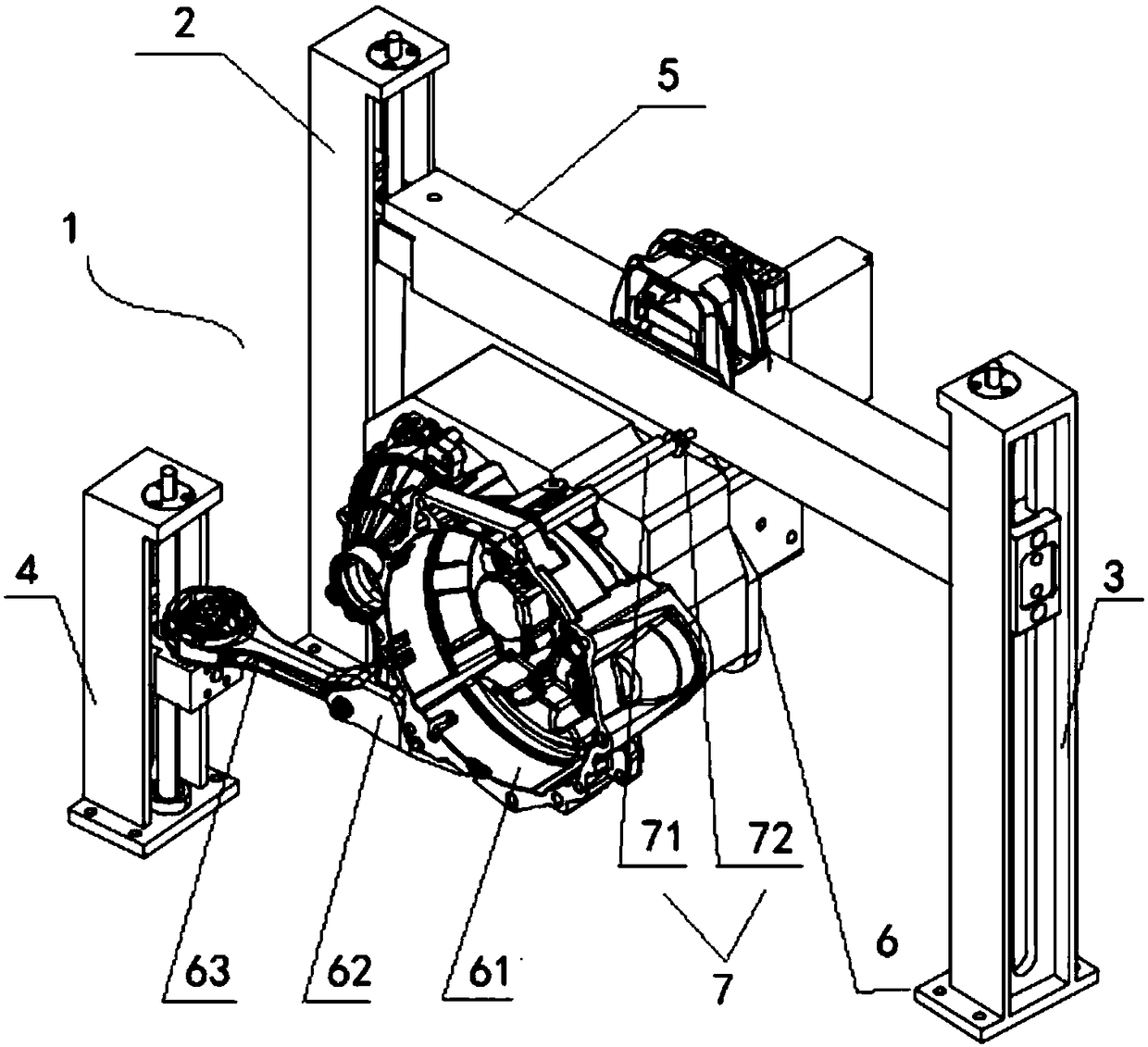
[0053] Embodiment 1. First refer to figure 1 , the present embodiment provides a kind of engine test stand, engine is installed on this test stand, just can carry out relevant various durability test and function test thereby evaluate the quality performance of engine. Before the test, the operator needs to install the engine on the engine test bench for installation preparation, and after the test, it needs to disassemble. The disassembly here includes the disassembly of the engine.
[0054] The engine test stand 1 in the present embodiment comprises a base (not shown), a first column 2, a second column 3, and a third column 4 that are vertically arranged on the base 9 and are arranged at an angle, and are connected to the first column. The beam 5 between the first column 2 and the second column 3 . The engine test bench 1 also includes a process gearbox 6 and an auxiliary device 7, one side of the process gearbox 6 is connected to the beam 5, and the other side is connected...
Embodiment 2
[0062] Embodiment 2. This embodiment provides a method of using the engine test bench based on Embodiment 1. The specific steps are as follows:
[0063] After the engine performance test is completed, the engine is removed from the engine test bench 1;
[0064] Add an auxiliary device 7 between the process gearbox 6 and the beam 5, so that the process gearbox 6 remains stable;
[0065] When the engine performance test needs to be carried out again, the engine is installed on the engine test bench 1, and the auxiliary device 7 is removed to perform the engine performance test.
[0066] Therefore, during specific operation, before and after the test, only the engine needs to be unloaded separately, and the process gearbox 6 still remains on the engine test bench 1, thereby reducing the steps of disassembling the process gearbox 6 and simplifying the process. Moreover, the disassembly and installation of the process gearbox 6 and the engine can be carried out on the engine test ...
Embodiment 3
[0074] Embodiment 3. First refer to Image 6 , this embodiment provides a general engine test bench, relative to Embodiment 1, the engine test bench in this embodiment is suitable for any type of engine.
[0075] further reference Figure 5 to Figure 9 , the auxiliary device 10 in this embodiment includes a first connecting piece 11, a second connecting piece 12 and an adjusting piece 13, one end of the second connecting piece 12 is vertically connected to the first connecting piece 11, and the other end of the second connecting piece 12 is connected to the beam 5 connections. Compared with Embodiment 1, this embodiment can adjust the longitudinal position of the auxiliary device 12 according to different engine structures by adding the second connecting piece 12.
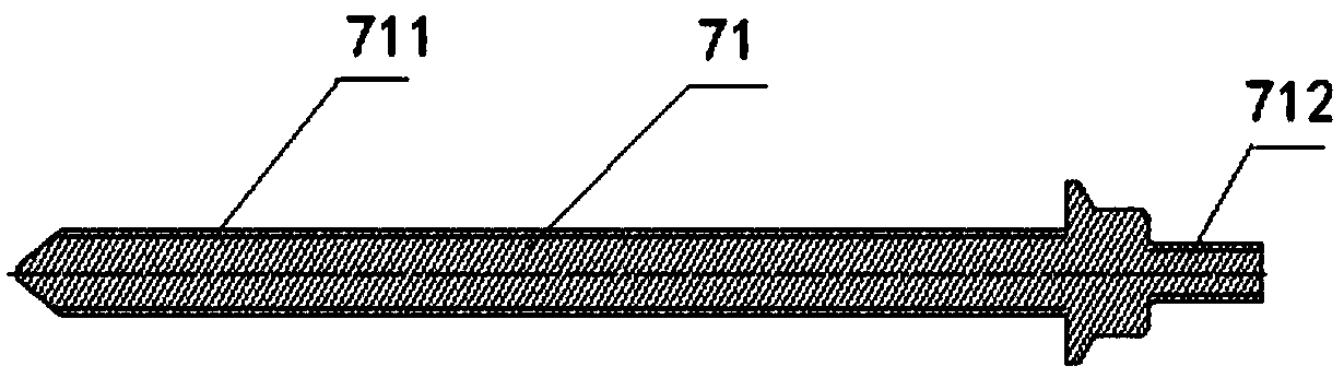
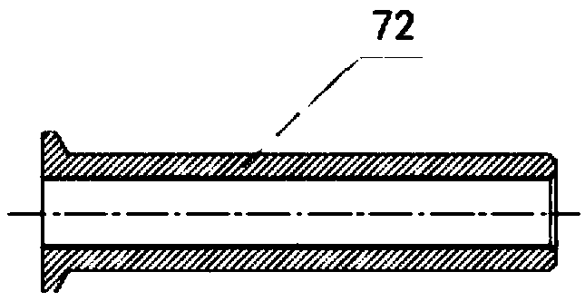
[0076] Wherein, the first connecting member 11 may be a reduced-diameter stud bolt or a reduced-diameter double-ended screw, and a reduced-diameter double-ended screw is preferred in this embodiment. The first con...
PUM
 Abstract
Description
Claims
Application Information
 - R&D
- Intellectual Property
- Life Sciences
- Materials
- Tech Scout
- Unparalleled Data Quality
- Higher Quality Content
- 60% Fewer Hallucinations
Browse by: Latest US Patents, China's latest patents, Technical Efficacy Thesaurus, Application Domain, Technology Topic, Popular Technical Reports.
© 2025 PatSnap. All rights reserved.Legal|Privacy policy|Modern Slavery Act Transparency Statement|Sitemap|About US| Contact US: help@patsnap.com