Multifunctional automatic tool changing numerical control engraving machine

A CNC engraving machine and automatic tool change technology, applied in engraving, decorative arts, processing models, etc., can solve the problems of easy errors, unguaranteed engraving quality, deformation, etc., to improve engraving efficiency, engraving quality and The effect of service life

Inactive Publication Date: 2018-12-21
UNIV OF ELECTRONICS SCI & TECH OF CHINA ZHONGSHAN INST
View PDF0 Cites 2 Cited by
  • Summary
  • Abstract
  • Description
  • Claims
  • Application Information

AI Technical Summary

Problems solved by technology

[0003] In the engraving work, due to the diversification of processing requirements, such as engraving shapes and engraving methods, the whole process often requires multiple processes and needs to be completed with different tools. Therefore, before the next engraving process, it is necessary to first Make the engraving machine stop running, and manually replace the tool with the size required for the next process on the cutter shaft, then restart the engraving machine and carry out the next engraving process, such a cycle The ordinary single-head engraving machines on the market often need to be manually carried out Tool disassembly and replacement operations, and, in order to ensure the quality of engraving after replacement, it is necessary to perform processes such as tool setting, positioning, and path change. These tool changing processes occupy a lot of working time, reduce work efficiency, and easily cause errors. There is no guarantee, and the design of the workpiece clamping part of the existing machine is generally to use a chuck at one end and a tip at the other end, so that it is easy to twist and deform the workpiece when processing small parts

Method used


Image

  • Multifunctional automatic tool changing numerical control engraving machine
  • Multifunctional automatic tool changing numerical control engraving machine
  • Multifunctional automatic tool changing numerical control engraving machine

Examples


Embodiment Construction

[0040] The following will clearly and completely describe the technical solutions in the embodiments of the present invention with reference to the accompanying drawings in the embodiments of the present invention. Obviously, the described embodiments are only some, not all, embodiments of the present invention. Based on the embodiments of the present invention, all other embodiments obtained by persons of ordinary skill in the art without making creative efforts belong to the protection scope of the present invention.

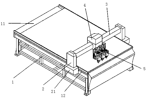
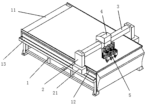
[0041] The embodiment of the present invention discloses a multi-functional automatic tool change CNC engraving machine, such as Figure 1-3 shown, including:

[0042] Frame 1, its upper part is provided with the workbench 11 that is used to place workpiece; Be arranged on the two sides of frame 1 and be connected with the lateral movement mechanism 2 that slides; The top of the side transverse movement mechanism 2 is fixedly connected; the crossbeam 3 is equ...


PUM


Abstract

The invention discloses a multifunctional automatic tool changing numerical control engraving machine. The multifunctional automatic tool changing numerical control engraving machine comprises a frame, transverse moving mechanisms, a cross beam, a longitudinal moving mechanism and an engraving mechanism. The engraving mechanism is composed of a plurality of tool spindle frames. Each tool spindle frame comprises a tool spindle. A lifting seat is arranged on the side, opposite to a vertical moving seat, of each tool spindle. A third sliding component is arranged on each lifting seat. A third guide rail matched with the corresponding third sliding component is arranged at the position, corresponding to the third sliding component, of the vertical moving seat. A tool chuck for installing a tool is fixed at the end of each tool spindle. According to the multifunctional automatic tool changing numerical control engraving machine, a heat dissipation and dust removal device and a laser detector are arranged, so that the tool engraving quality is improved, the service life of the tool is prolonged, and the precision of the tool displacement is improved; and the tool changing operation can be automatically realized in the whole engraving process without manned shut-down, and the engraving efficiency is improved.

Description

technical field [0001] The invention relates to the technical field of engraving equipment, and more specifically relates to a multifunctional automatic tool-changing numerical control engraving machine. Background technique [0002] Mechanical engraving machine is a general-purpose mechanical equipment widely used in wood industry, advertising industry, craft industry, mold industry, construction industry, printing and packaging industry, decoration industry, and can carve woodworking board, density board, acrylic organic board, PVC board, Hibiscus board, two-color board, marble, fireproof board, rubber board, glass and other different materials. [0003] In the engraving work, due to the diversification of processing requirements, such as engraving shapes and engraving methods, the whole process often requires multiple processes and needs to be completed with different tools. Therefore, before the next engraving process, it is necessary to first Make the engraving machine...

Claims


Application Information

Patent Timeline
IPC IPC(8): B44B1/00B44B1/06B44B3/00B44B3/06
CPCB44B1/003B44B1/06B44B3/006B44B3/06
Inventor 夏百战
Owner UNIV OF ELECTRONICS SCI & TECH OF CHINA ZHONGSHAN INST
Why Eureka
Try Eureka