
Flow-control and variable-temperature spray drying system

A drying system, spray drying tower technology, applied in spray evaporation, evaporator accessories and other directions, can solve the problems of increasing the difficulty of transportation and installation, increasing production costs, economic losses, etc., to ensure no cross-contamination, improve product yield, The effect of reducing labor intensity

Pending Publication Date: 2018-12-21
吴际
View PDF4 Cites 4 Cited by
  • Summary
  • Abstract
  • Description
  • Claims
  • Application Information

AI Technical Summary

Problems solved by technology

[0003] During the actual operation of this kind of spray tower, the atomization range of the material liquid will change due to factors such as the change of the material liquid pressure and the wear of the material liquid atomization device, so that the atomized droplets deviate from the design area and move irregularly.
At the same time, the fluctuation of external gravitational force and the poor effect of the air equalizing plate will cause changes in the distribution of hot air and turbulence in the air flow of hot air. When the two are superimposed, the range of downward ejection of hot air will not be able to cover the atomization of the atomizing device. The range of the drying effect is not good, the moisture content of the material is uneven, and many small atomized particles will float to the wall of the tower body at the same time, causing the wall to stick; the sticking amount of some materials can reach about 10%.
First of all, it affects the yield of the product, causing great economic losses; secondly, because the material sticking to the wall is in a dry environment for a long time, the moisture content is lower than that of the normal material, and it is easy to burn; the color will also be different from the normal material, and the sticking The wall is easy to agglomerate, once the material sticking to the wall falls off, it will affect the quality of the normal material
In addition, at the end of each production cycle, the drying tower needs to be cleaned. The sticky wall causes a large cleaning workload and a larger amount of cleaning wastewater, which increases production costs and increases the risk of environmental pollution.
[0004] Some designers intentionally increase the diameter of the tower body in order to reduce the amount of material sticking to the wall during design, so that the liquid droplets cannot reach the inner wall.
The diameter of the tower usually reaches several meters, and the height is even tens of meters, which virtually increases the manufacturing cost and increases the difficulty of transportation and installation.
In addition, after the droplet is sprayed, the speed in the direction of the cylinder wall is attenuated to a certain value so as not to touch the cylinder wall. The droplet velocity is affected by the pressure of the feed liquid and the size of the nozzle hole, which is a constantly changing value. Although the spray towers currently on the market Some have increased the diameter of the tube, but it is also impossible to avoid the phenomenon that the liquid droplets stick to the wall of the tube.
[0005] At present, the energy consumption of the spray tower is relatively large, mainly because the exhaust gas discharge temperature is also high while pursuing the drying intensity, usually at 70-90°C, and some high-temperature drying exhaust gas discharge temperatures are higher, and in most cases, the exhausted heat accounts for 10%. More than 50% of the total drying heat, resulting in a great waste of energy

Method used


Image

  • Flow-control and variable-temperature spray drying system
  • Flow-control and variable-temperature spray drying system
  • Flow-control and variable-temperature spray drying system

Examples


Embodiment Construction

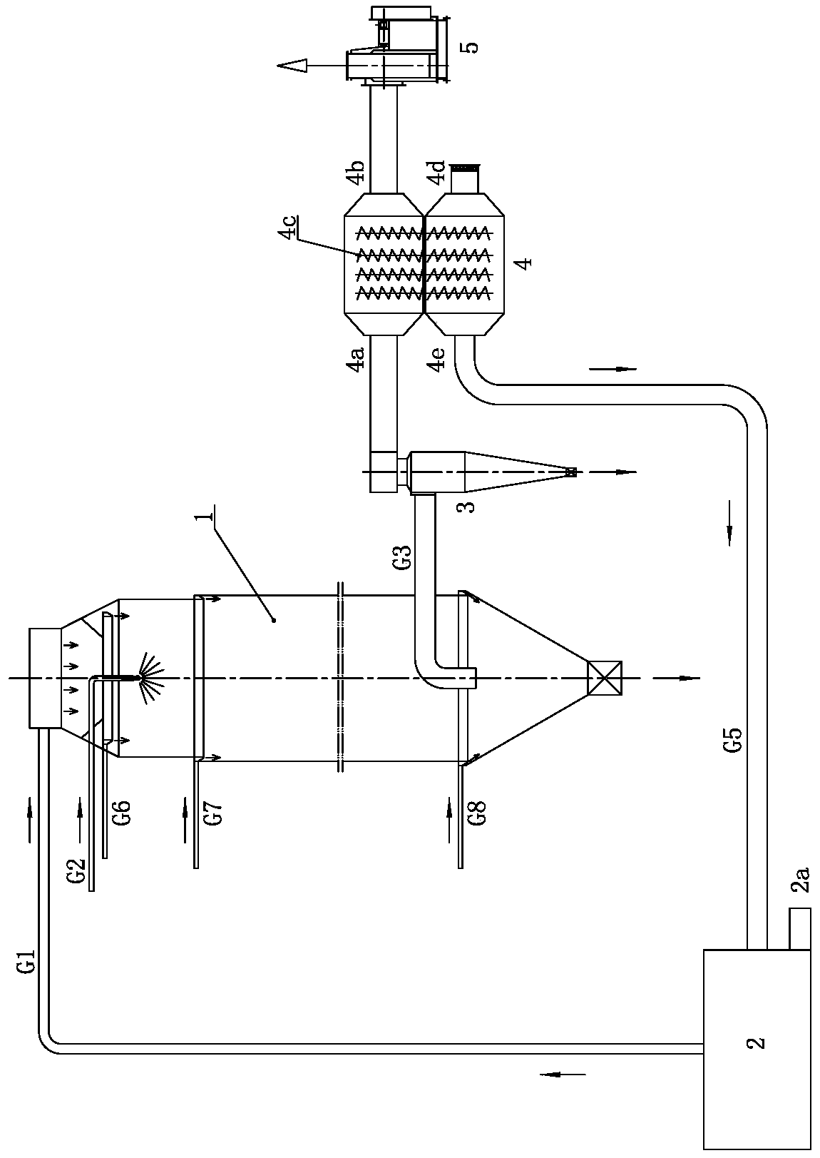
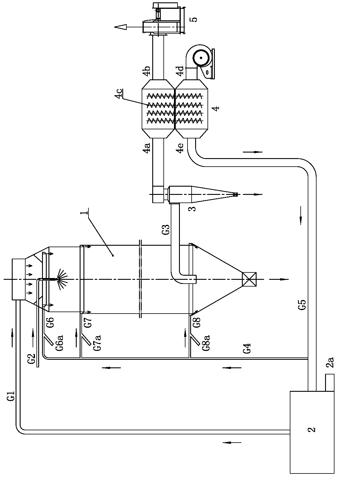
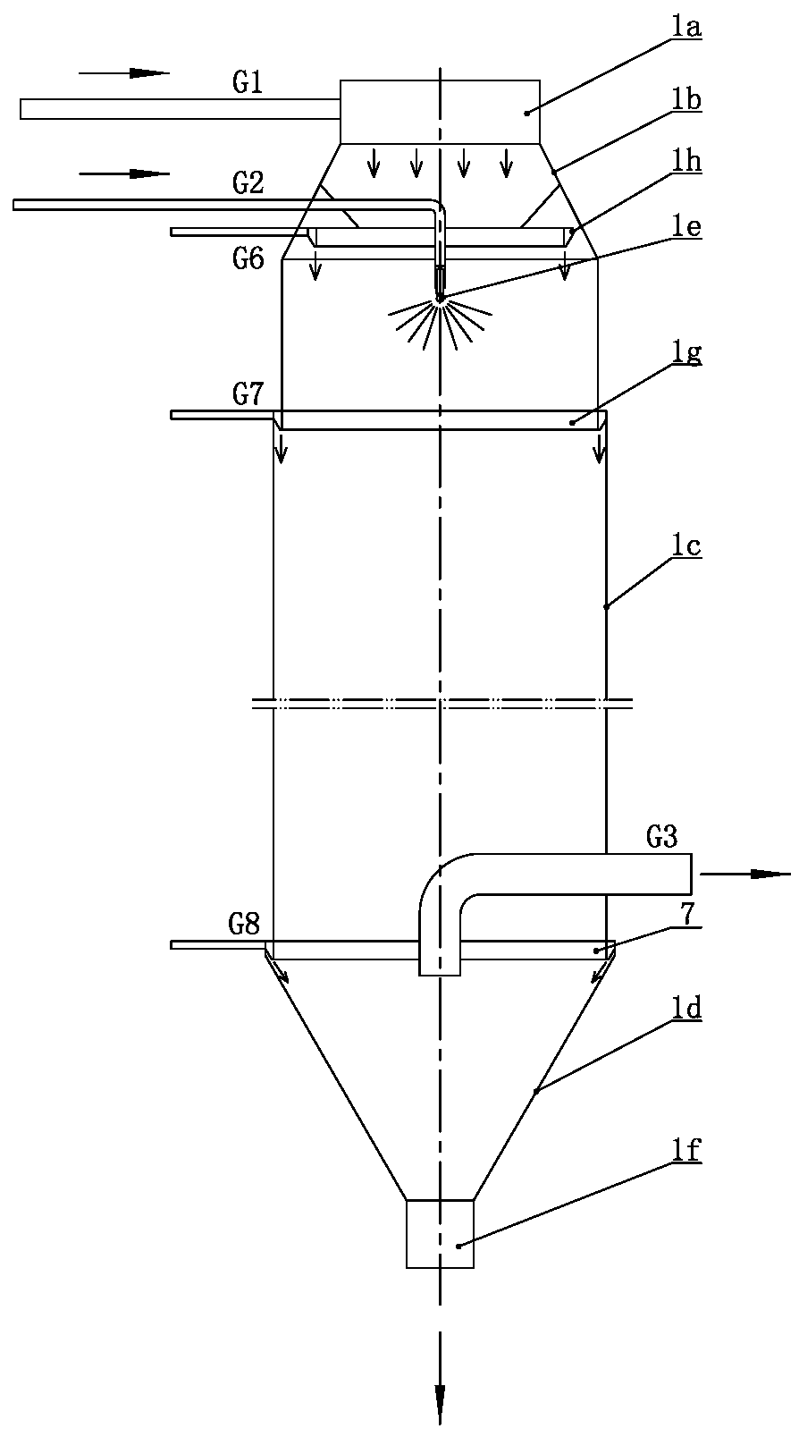
[0025] like Figure 1 to Figure 6 As shown, the spray drying system with flow control and variable temperature of the present invention includes a heating device 2, a spray drying tower 1 and an induced draft fan 5, and the spray drying tower 1 includes an air equalizing section 1a connected in sequence from top to bottom and coaxial, and a cone on the tower. 1b, cylinder 1c and lower cone 1d, the side wall of the uniform air section 1a is connected to the tower body hot air main pipe G1, the side wall of the tower upper cone 1b is connected to the feed liquid pipe G2, and the inner end of the feed liquid pipe G2 is connected to the feed liquid The atomization device 1e is connected, and the material liquid atomization device 1e is located on the axis of the cylinder 1c. The lower end of the cylinder 1c is connected to the tower body exhaust pipe G3, and the inner end of the tower body exhaust pipe G3 can extend to the axis of the cylinder body And the port turns downward, the...


PUM


Abstract

The invention relates to a flow-control and variable-temperature spray drying system which comprises a heating device, a spray drying tower and an induced draft fan, wherein the spray drying tower comprises an uniform-air section, a tower upper cone, a barrel and a lower cone body from top to bottom; the side wall of the uniform-air section is connected with a tower body hot-blast main pipe; the side wall of the tower upper cone is connected with a feed liquid pipe; the inner end of the feed liquid pipe is connected with a feed liquid atomizing device; the feed liquid atomizing device is positioned on the axis of the barrel; the lower end of the barrel is connected with a tower body exhaust pipe; a finished product discharge valve is mounted at a lower port of the lower cone body; an air outlet of the heating device is connected with the tower body hot-blast main pipe; at least one barrel rectifying ring capable of forming an annular downward air flow on the inner wall of the barrel ismounted on the circumference of the barrel of the spray drying tower; the barrel rectifying ring is coaxial with the barrel; the outer side wall of the barrel rectifying ring is connected with a barrel rectifying ring blast pipe; a plurality of temperature gradients are formed in the tower body from top to bottom. The spray drying system can avoid wall sticking and realize online variable-temperature control, and the product has the advantages of high yield and good quality.

Description

technical field [0001] The invention relates to a drying device, in particular to a flow-controlled and variable-temperature spray drying system, which belongs to the technical field of spray drying equipment. Background technique [0002] The spray drying equipment used in the field of additives, pesticides and food processing in the prior art is generally in the form of a cylindrical tower body, which consists of an air uniform section, an upper cone, a cylinder body, a lower cone body, a material liquid atomization device, The tower body consists of a tower body exhaust pipe and a finished product discharge valve. The dry hot air enters the upper cone of the tower from the air equalizing section through the air equalizing plate, flows downward under the external gravitational force of the tower body exhaust pipe, flows through the cylinder, and is discharged from the tower body exhaust pipe at the lower part of the tower body. Under the action of the pressure pump, the f...

Claims


Application Information

Patent Timeline
IPC IPC(8): B01D1/18B01D1/20B01D1/30
CPCB01D1/18B01D1/20B01D1/30
Inventor 吴际高添
Owner 吴际
Learn More