A High Precision Temperature Sensor
A temperature sensor, high-precision technology, applied in thermometers, thermometers with physical/chemical changes, instruments, etc., can solve the problems of signal phase-frequency characteristics, unfavorable optical fiber sensors, and variable frequency, etc., to achieve small phase detection errors , Wide range of applications, reliable results
- Summary
- Abstract
- Description
- Claims
- Application Information
AI Technical Summary
Problems solved by technology
Method used
Image

Examples
Embodiment 1
[0026] Example 1 Overall structure of the present invention
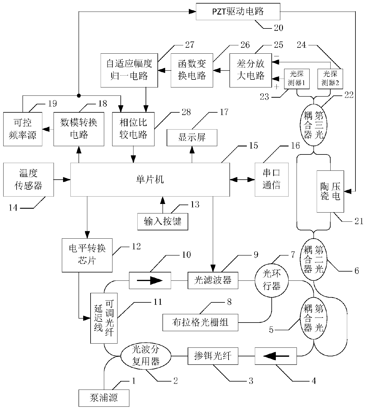
[0027] Such as figure 1 As shown, the overall structure of the present invention has: pump source 1 (LC962U pump source of OCLARO company, center wavelength 980nm, maximum single-mode output optical power of 750mW) and optical wavelength division multiplexer 2 (COMCORE company 980 / 1060nm The 980nm end of the single-mode fiber wavelength division multiplexer) is connected, and the 1550nm end of the optical wavelength division multiplexer 2 is connected to the delay line adjustable fiber 11 (VDL-40-15-S9-1-FA of Sichuan Yuxingxing Optical Technology Co., Ltd. Type electric optical fiber delay line) is connected to one end, the other end of the delay line adjustable light 11 is connected to the input end of the first optical isolator 10 (1550nm polarization-independent optical isolator), and the control end of the delay line adjustable light 11 is connected to the electric The output port of the level conversion chip 12 ...
Embodiment 2
[0029] Example 2 Function Conversion Circuit
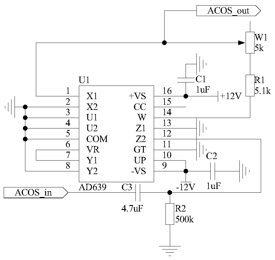
[0030] Such as figure 2 As shown, the structure of the function conversion circuit 26 used in the present invention is that one end of the capacitor C3 is connected to the pin 12 of the trigonometric function converter U1 and one end of the resistor R2, and the other end of the capacitor C3 is used as the input end of the function conversion circuit 26 , Marked as port ACOS_in, connected to the output end of the differential amplifier circuit 25; the other end of the resistor R2 is grounded; the pins 2, 3, 4, 5, 8, 11, and 13 of the trigonometric function converter U1 are grounded, and the pins 9, 10 is connected to one end of capacitor C2 and -12V power supply, and the other end of capacitor C2 is grounded; pin 6 of trigonometric function converter U1 is connected to pin 7, pin 16 is connected to +12V power supply and one end of capacitor C1, capacitor C1 The other end of the trigonometric function converter U1 is connected to the ...
Embodiment 3
[0031] Embodiment 3 Adaptive amplitude normalization circuit
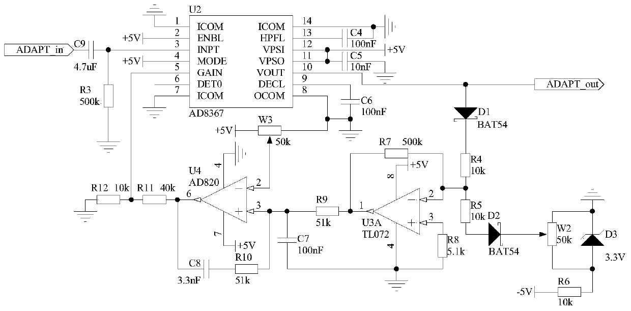
[0032] Since the amplitude of the signal output by the function conversion circuit 26 is small and is affected by multiple parameters in the optical path and the circuit, the magnitude is uncertain. Therefore, the present invention designs an adaptive amplitude normalization circuit 27 to convert the signal output by the function conversion circuit 26. The amplitude of is normalized to the optimal size to further improve the accuracy of demodulation. The structure of the adaptive amplitude normalization circuit 27 is that one end of the capacitor C9 is connected to one end of the resistor R3 and the pin 3 of the chip U2, the other end of the resistor R3 is grounded, and the other end of the capacitor C9 is used as the adaptive amplitude. The input terminal of circuit 27, marked as port ADAPT_in, is connected to port ACOS_out of function conversion circuit 26; pin 1, pin 7, pin 8, and pin 14 of chip U2 are all grounded...
PUM
 Abstract
Description
Claims
Application Information
 - Generate Ideas
- Intellectual Property
- Life Sciences
- Materials
- Tech Scout
- Unparalleled Data Quality
- Higher Quality Content
- 60% Fewer Hallucinations
Browse by: Latest US Patents, China's latest patents, Technical Efficacy Thesaurus, Application Domain, Technology Topic, Popular Technical Reports.
© 2025 PatSnap. All rights reserved.Legal|Privacy policy|Modern Slavery Act Transparency Statement|Sitemap|About US| Contact US: help@patsnap.com