Injection and ignition system of direct injection rotary engine with variable ignition position

A rotary engine and in-cylinder direct injection technology, applied to internal combustion piston engines, combustion engines, machines/engines, etc., can solve the problems of difficult ignition, difficult to achieve compression ignition, small compression of rotary engines, etc., to improve combustion efficiency and increase Ignition quality and the effect of improving power performance

Active Publication Date: 2020-06-26
JIANGSU UNIV
View PDF16 Cites 0 Cited by
  • Summary
  • Abstract
  • Description
  • Claims
  • Application Information

AI Technical Summary

Problems solved by technology

This is mainly due to 1) due to its own structural limitations, the compression ratio of the rotary engine is small, and it is difficult to achieve compression ignition, so the rotary engine using in-cylinder direct injection technology needs an auxiliary ignition device to ignite the fuel; 2) the airflow in the cylinder of the rotary engine is It moves with the rotation direction of the rotor, that is to say, the airflow inside the combustion chamber generally flows in one direction, and there is no sharply changing eddy flow and tumble flow in the cylinder. This flow field itself is not conducive to the rapid atomization and diffusion of fuel. ; 3) The traditional rotary engine uses a spark plug to ignite. This ignition method first makes the mixture near the spark plug form a fire core, and then the flame spreads around under the action of the flow field and the movement of the mixture.
However, it is difficult for the fuel injected by the direct injection rotary engine to completely mix with the air, and the long and narrow combustion chamber of the rotary engine will inevitably cause the flame to travel a long distance after the spark plug is ignited to completely burn the mixture in the combustion chamber. Greatly limits the improvement of combustion efficiency; 4) The ignition position of the traditional spark plug ignition method is fixed, so it is difficult to match the distribution position of fuel under various fuel injection conditions, resulting in difficulty in ignition

Method used


Image

  • Injection and ignition system of direct injection rotary engine with variable ignition position
  • Injection and ignition system of direct injection rotary engine with variable ignition position
  • Injection and ignition system of direct injection rotary engine with variable ignition position

Examples


Embodiment Construction

[0022] The present invention will be further described below in conjunction with the accompanying drawings and specific embodiments, but the protection scope of the present invention is not limited thereto.

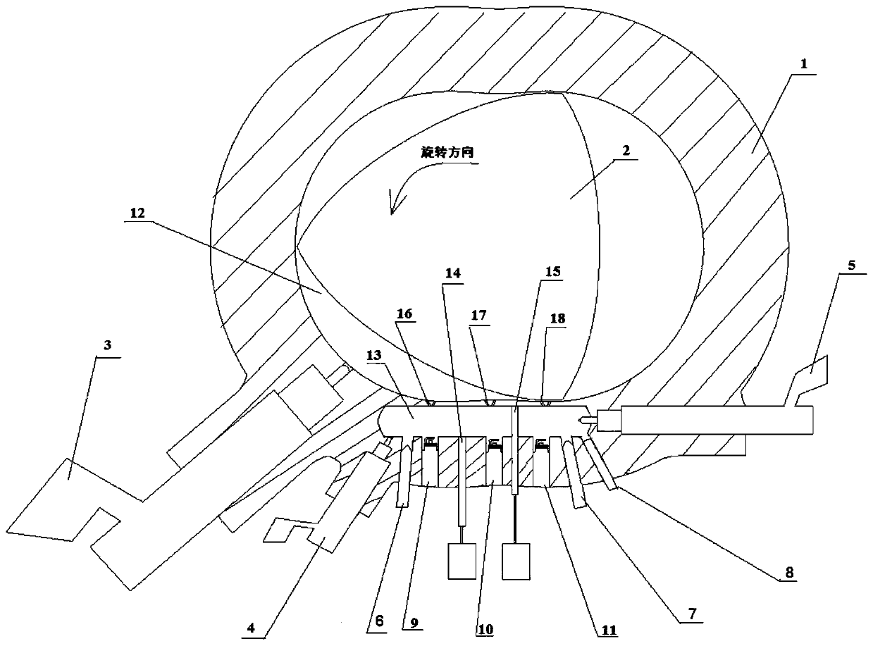
[0023] Such as figure 1 As shown, the in-cylinder direct injection rotary engine injection ignition system with variable ignition position according to the present invention includes a rotary engine cylinder wall 1, a combustion chamber and a triangular rotor 2, and the combustion chamber is located on the rotary engine cylinder wall 1 Between the triangular rotor 2; the combustion chamber is divided into the first combustion chamber, the second combustion chamber 12 and the third combustion chamber by the triangular rotor 2, the first combustion chamber is in the intake stroke, and the second combustion chamber is in the power stroke and the third combustion chamber are in the exhaust stroke, and the volumes of the first combustion chamber, the second combustion chamber ...


PUM


Abstract

The invention provides an in-cylinder direct injection rotor engine injection ignition system with a variable ignition position. The system comprises a rotor engine steam cylinder wall, a combustion chamber and a triangular rotor; the combustion chamber is located between the rotor engine steam cylinder wall and the triangular rotor, a main fuel injector inserted into a second combustion chamber is mounted on the rotor engine steam cylinder wall, a pre-combustion chamber, an auxiliary fuel injector and an ignition plug are further included, the pre-combustion chamber is located in the rotor engine steam cylinder wall, the pre-combustion chamber communicates with the second combustion chamber, the auxiliary fuel injector and the ignition plug inserted into the pre-combustion chamber are arranged on the rotor engine steam cylinder wall, and an air nozzle is arranged on the pre-combustion chamber. Flame diffusion and high-temperature are used for igniting main injection fuel oil in the main combustion chamber, the fuel ignition quality is improved, the engine combustion efficiency is improved, and the engine power performance is improved.

Description

technical field [0001] The invention relates to the technical field of rotary engines, in particular to an injection and ignition system for an in-cylinder direct-injection rotary engine with variable ignition positions. Background technique [0002] As with any internal combustion engine, the combustion process of the fuel in the combustion chamber determines its thermal efficiency and the level of pollutant emissions. This is because only a good combustion process can make the fuel fully burn and release heat, so as to achieve higher thermal efficiency, better power performance and lower unburned hydrocarbon emissions. The ignition process of the fuel plays a key role in the formation and spread of the flame. Igniting the fuel with sufficient ignition energy at a suitable position can effectively increase the combustion efficiency of the fuel. Therefore, it is very necessary to design an advanced ignition method for internal combustion engines. , which is a common problem...

Claims


Application Information

Patent Timeline
Patent Type & Authority Patents(China)
IPC IPC(8): F02B53/12F02B55/14
CPCF02B53/12F02B55/14Y02T10/12
Inventor 陆尧潘剑锋范宝伟陈伟倪靖
Owner JIANGSU UNIV
Why Eureka
Try Eureka