
Machining and positioning combination fixture for thin-walled part with threaded hole

A technology of thin-walled parts and threaded holes, which is applied in the field of parts processing and positioning tooling and fixtures, can solve the problems of processing accuracy, coaxiality and taper runout, which are difficult to meet processing requirements, easy to crush threads, and difficult to clamp. Achieve good economical practicability and popularization, improve machining accuracy and coaxiality, and facilitate and quick installation.

Pending Publication Date: 2018-12-18
GUIZHOU HANGSHUO IND CO LTD
View PDF23 Cites 3 Cited by
  • Summary
  • Abstract
  • Description
  • Claims
  • Application Information

AI Technical Summary

Problems solved by technology

[0002] At present, in the processing of many thin-walled workpieces such as pipe sleeves, the outer surface is turned by CNC lathes. When the external shape accuracy, coaxiality, and taper runout of thin-walled workpieces are required to be high, rigid mandrels are often used. When processing, the rigid mandrel is inserted into the shaft hole of the thin-walled workpiece, and the inner surface of the hole is used for positioning, but the rigid mandrel of this type of fixture and the inner hole of the workpiece are installed with clearance fit, and the positioning Low precision makes it difficult to meet the processing requirements for machining accuracy, coaxiality and taper runout; and there are problems such as difficult clamping, slipping during cutting, and low production efficiency.
Especially when the shaft hole of the thin-walled workpiece (especially thin-walled small workpiece) is a threaded hole, the use of mandrel fixtures not only has a large installation gap, but also causes large processing errors, and is easy to press during clamping and processing. Injury to the thread, in severe cases, the workpiece will be scrapped, resulting in material and financial losses

Method used


Image

  • Machining and positioning combination fixture for thin-walled part with threaded hole
  • Machining and positioning combination fixture for thin-walled part with threaded hole
  • Machining and positioning combination fixture for thin-walled part with threaded hole

Examples


Embodiment Construction

[0016] The following will clearly and completely describe the technical solutions in the embodiments of the present invention in conjunction with the accompanying drawings in the embodiments of the present invention:

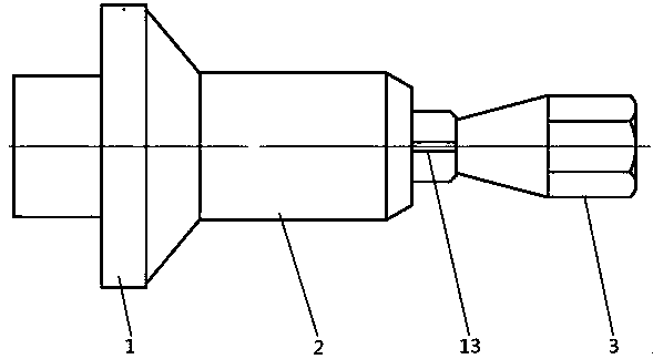
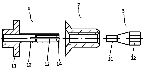
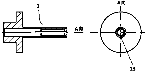
[0017] like Figure 1~Figure 3 As shown, a combination fixture for machining and positioning of thin-walled parts with threaded holes is used for clamping and positioning of thin-walled parts 2 such as pipe sleeves. The axis of the thin-walled parts 2 is provided with a threaded through hole, which includes Specifically 1 and the expansion body 3, the expansion body 3 is screwed into the clamp body 1, specifically, the clamp body 1 is a limit end 11 and a clamping rod 12 of an integral structure made of spring steel Composition, the clamping rod 12 is a hollow structure, the outer surface of the clamping rod 12 is provided with external threads that match the threaded holes of the thin-walled parts 2, preferably, the outer diameter of the thread on the outer sur...


PUM


Abstract

The invention discloses a machining and positioning combination fixture for a thin-walled part with a threaded hole. The machining and positioning combination fixture comprises a fixture body and a swelling body. The fixture body is composed of a limiting end head and a clamping rod of a hollow structure. An external thread matched with the threaded hole of the thin-walled part is arranged on theouter circle surface of the clamping rod, and an internal thread is arranged on an inner hole of the clamping rod. The clamping rod is further provided with a cut groove. The swelling body is composedof a pulling and twisting end head and a swelling core. An external thread matched with the internal thread of the clamping rod is arranged on the outer surface of the swelling core. The swelling body is connected into the fixture body in a sleeved mode through the threads. During installation, the thin-walled part is penetrated into the clamping rod of the fixture body, then the swelling core ofthe swelling body is twisted into the inner threaded hole of the clamping rod, the clamping rod can be swelled along the cut groove in the twisting-in process, and thus swelling fixation is realized.The structure is simple, manufacturing cost is low, installation is convenient, fast, firm and reliable, and meanwhile the threads cannot be damaged by jamming; and moreover, installation coaxialityis high, and the machining precision and coaxiality of the part are effectively improved.

Description

technical field [0001] The invention relates to a thin-walled part processing and positioning combined fixture with threaded holes, which belongs to the field of part processing and positioning tooling and fixtures. Background technique [0002] At present, in the processing of many thin-walled workpieces such as pipe sleeves, the outer surface is turned by a CNC lathe. When the external shape accuracy, coaxiality, and taper runout of thin-walled workpieces are required to be high, rigid mandrels are often used. When processing, the rigid mandrel-like fixture is inserted into the shaft hole of the thin-walled workpiece, and the inner surface of the hole is used for positioning, but the rigid mandrel of this kind of fixture and the inner hole of the workpiece are installed with clearance fit, and the positioning The low precision makes it difficult to meet the processing requirements for machining accuracy, coaxiality and taper runout; and there are problems such as difficult...

Claims


Application Information

Patent Timeline
IPC IPC(8): B23Q3/06
CPCB23Q3/065
Inventor 龚少梅马世杰李昭桂
Owner GUIZHOU HANGSHUO IND CO LTD
Learn More