Home miniature sound wave cleaning machine

A sonic cleaning and miniature technology, which is applied in the direction of cleaning methods using liquids, chemical instruments and methods, cleaning methods and utensils, etc., can solve the problems of low efficiency of acoustic and electric replacement, low cleaning efficiency, inconvenience, etc., and improve the sound insulation effect , Reduce working noise and improve stability

Active Publication Date: 2018-12-18
南京声为技术有限公司
View PDF10 Cites 0 Cited by
  • Summary
  • Abstract
  • Description
  • Claims
  • Application Information

AI Technical Summary

Problems solved by technology

Among them, the acoustic-electric replacement efficiency of the piezoelectric ceramic sheet is low, resulting in a weak cavitation effect in the cleaning solution, and the cleaning effect is only distributed between 0 and 2 cm from the ultrasonic emitting end surface; and it is inconvenient to manually hold it close to the stained end; The cleaning efficiency is low and time-consuming, and it is difficult to achieve the ideal cleaning effect for heavily oily surfaces
Although the acoustic-electric conversion efficiency of the single piezoelectric ceramic transducer has been improved, it still needs to be manually held to clean some stains, and the uniformity of the sound field is not good, so it cannot effectively clean large and stained items
[0004] To sum up, although the current trough-type ultrasonic cleaning equipment has mature technology and strong sound field strength, it is difficult to meet the requirements of household cleaning equipment in terms of portability and sound field uniformity.
Although the external radiation type ultrasonic cleaning equipment is small in size, the technology is not mature at present, and there is no good solution in terms of sound field intensity, sound field uniformity, cleaning efficiency and portability.

Method used


Image

  • Home miniature sound wave cleaning machine
  • Home miniature sound wave cleaning machine
  • Home miniature sound wave cleaning machine

Examples


Embodiment

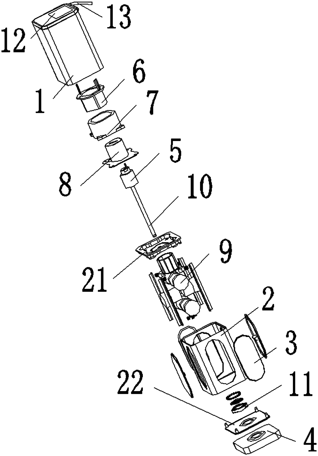
[0032] see Figure 1-7 , the present invention provides the following technical solutions: a household miniature acoustic wave cleaning machine, comprising a base 4, the upper end of the base 4 is placed with a lower casing 2, the side of the lower casing 2 is integrally formed with a steel plate 3, and the inner wall of the steel plate 3 is fixed with an ultrasonic transducer 9, the lower casing 2 also includes the upper end surface 21 of the lower casing and the lower end surface 22 of the lower casing, a waterproof slip ring is arranged above the lower casing 2, and an outer rotor stepping motor is placed inside the waterproof slip ring, and the lower casing An upper housing 1 is placed above the upper housing 1. In this embodiment, the upper housing 1 integrates an ultrasonic generator circuit system, a motor drive circuit, a control circuit, etc., and the upper housing 1 is highly integrated with an ultrasonic generator circuit system and a motor drive circuit. As well as...


PUM


Abstract

The invention relates to a home miniature sound wave cleaning machine comprising a base. A lower shell is placed at the upper end of the base, the side face of the lower shell is provided with an integrally-formed steel plate, an ultrasonic transducer is fixed to the inner wall of the steel plate, the lower shell further includes a lower shell upper end surface and a lower shell lower end surface,a waterproof sliding ring is arranged above the lower shell, an outer rotor stepping motor is arranged inside the waterproof sliding ring, and an upper shell is placed above the lower shell. The waterproof sliding ring comprises a sliding ring outer layer rotor and a sliding ring inner layer stator connected to the sliding ring outer layer rotor in a sleeved manner, the bottom end of the slidingring outer layer rotor is fixedly connected with the lower shell upper end surface, the outer rotor stepping motor comprises a stepping motor outer rotor and a stepping motor inner stator sleeved withthe interior of the stepping motor outer rotor, the bottom end of the stepping motor outer rotor is fixedly connected with the lower shell upper end surface, and a waterproof rotating device is arranged below the lower shell. The home miniature sound wave cleaning machine has the characteristics of high sound field strength, the uniform sound field and the high cleaning efficiency.

Description

technical field [0001] The invention belongs to the technical field of cleaning equipment, in particular to a household miniature sonic cleaning machine. Background technique [0002] Ultrasonic cleaner is an instrument used to remove pollutants. It uses a transducer to replace the sound energy of a power ultrasonic frequency source with mechanical vibration to clean objects. It is widely used in industry, national defense, biomedicine, etc. The principle of ultrasonic cleaning is mainly that the transducer converts the sound energy of the ultrasonic frequency source into mechanical vibration. The ultrasonic wave will produce ultrasonic cavitation effect during the propagation process in the cleaning liquid, and the microbubbles produced by ultrasonic cavitation will produce Micro-shock wave, micro-jet and local high temperature and high pressure, so as to realize the cleaning of the solid surface immersed in the cleaning liquid. [0003] At present, the development of port...

Claims


Application Information

Patent Timeline
Patent Type & Authority Applications(China)
IPC IPC(8): B08B3/12
CPCB08B3/12Y02B40/00
Inventor 张新王建超张宗波赵佳伟
Owner 南京声为技术有限公司
Why Eureka
Try Eureka