Intelligent ceramic rotary valve

A technology of rotary valves and ceramics, applied in valve details, valve devices, valve housing structures, etc., can solve problems such as pipeline blockage, and achieve the effects of high hardness and wear resistance, strong cleaning force, and novel structure

Pending Publication Date: 2020-05-15
郑州市新玉源机械工业有限公司
View PDF0 Cites 0 Cited by
  • Summary
  • Abstract
  • Description
  • Claims
  • Application Information

AI Technical Summary

Problems solved by technology

[0003] The purpose of the present invention is to provide an intelligent ceramic rotary valve to solve the problem of pipeline blockage caused by powder agglomeration in the pipeline or slurry crystallization and gelation in the prior art. The intelligent ceramic rotary valve has a novel structure and can Timely eradicate and scrape the clogging, crystallization and gelation of slurry and powder on the pipe wall to prevent clogging continuously, and can obtain the operating status of each valve body in real time and collect them on the cloud on an enterprise basis, providing enterprises with cloud Data sharing and value-added services to realize system intelligence

Method used


Image

  • Intelligent ceramic rotary valve
  • Intelligent ceramic rotary valve
  • Intelligent ceramic rotary valve

Examples


Embodiment 1

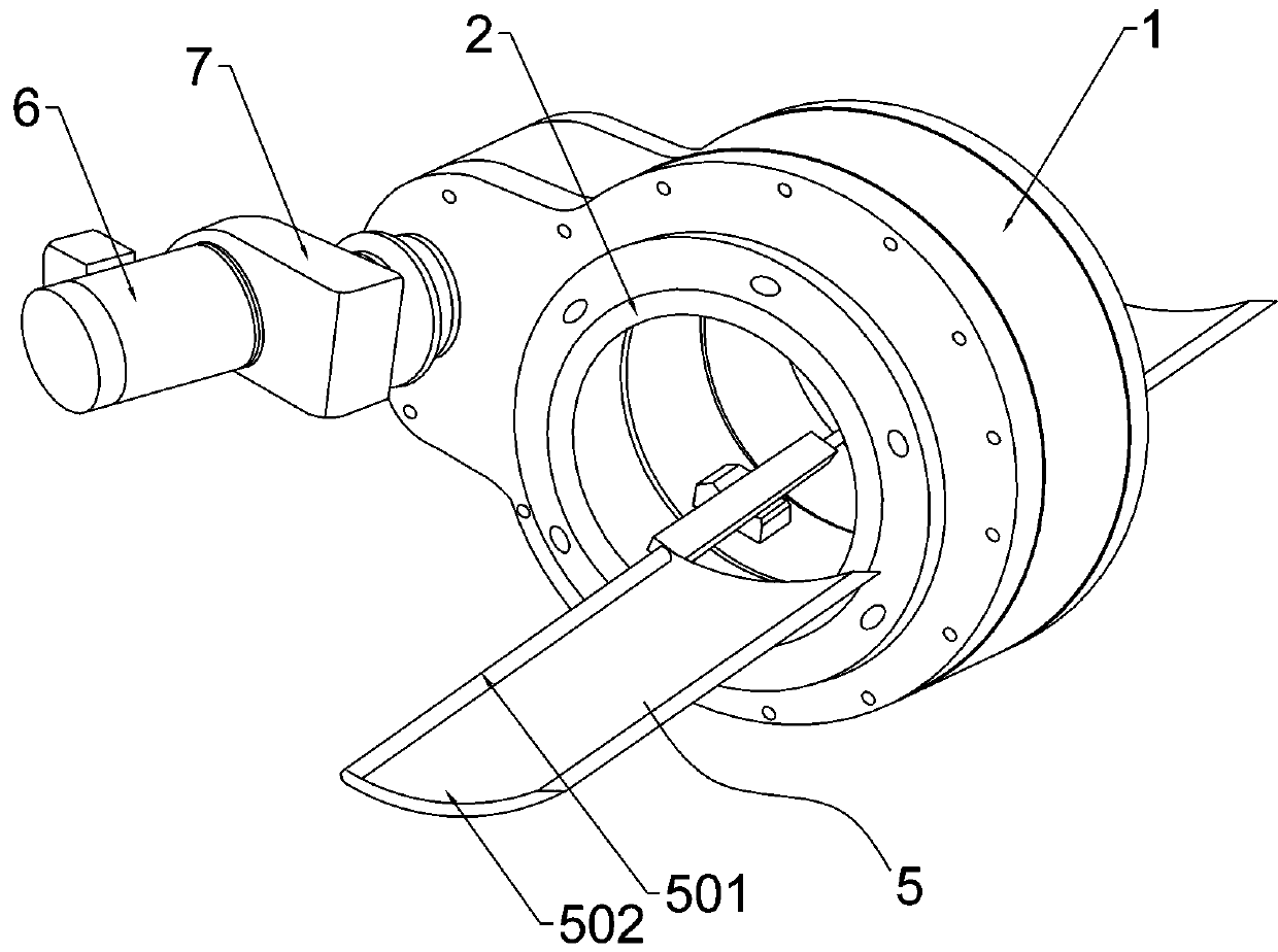
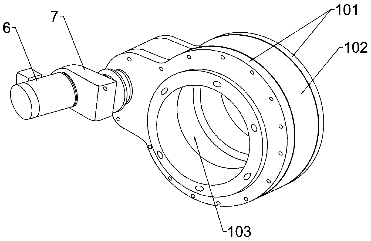
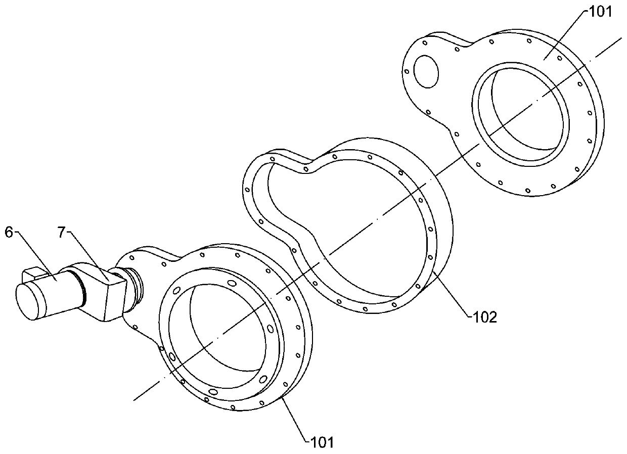
[0034] Example 1: An intelligent ceramic rotary valve, such as Figure 1-10 As shown, the valve body 1 is included. The valve body includes two main casings 101 and an intermediate casing 102. The intermediate casing is located between the two main casings. The outer ends of the two main casings are integrally provided with flange end faces. Used to connect the conveying pipeline 13, the inner ends of the two main shells 101 are respectively symmetrically bolted on both sides of the middle shell 102, so that a valve tube and a valve cavity are formed in the valve body. The central axes are parallel to each other; because the intermediate housing 102 is sandwiched between the two main housings 101, an annular gap 103 can be formed on the wall of the valve tube, and the width of the annular gap is equal to the width of the intermediate housing 102 , The valve tube and the valve cavity are kept in communication with each other through the annular gap 103. The purpose of this desig...

Embodiment 2

[0042] Embodiment 2: An intelligent ceramic rotary valve of this embodiment, and the description is centered on the difference from Embodiment 1.

[0043] When the small-scale transportation pipeline 13 has cost requirements or space constraints, the motor rotation can be replaced by manual rotation, such as Picture 9 As shown, in this embodiment, the power mechanism includes a rotating rod 8 and a manual crank 9. The inner end of the rotating rod 8 is connected to the axle of the power output gear 4, and the manual crank 9 rotates to drive the transmission ring 3 and the rotating bushing 202 rotates, and the worker regularly rotates the manual crank 9 to clean the inner wall of the conveying pipe 13 regularly.


PUM


Abstract

The invention relates to the field of pipelines, in particular to an intelligent ceramic rotary valve. The intelligent ceramic rotary valve comprises a valve body, a bush and a power mechanism. The bush is a ceramic bush, and the bush comprise a rotary bush bod and fixed bush bodies. Inner cavities of the rotary bush body and the fixed bush bodies communicate to form a conveying pipe cavity. The rotary bush body and the power mechanism are in transmission connection. A boosting rod and a peeling-off blade are mounted on the inner wall of the rotary bush body. The boosting rod is arranged on the inner wall of the rotary bush body in the axial direction, one side of the peeling-off blade is mounted on the boosting rod, and a peeling-off slope is arranged on the other side of the peeling-offblade and is in contact with the inner wall of the rotary bush body. Pipe wall obstructions can be removed in time, and continuous blocking prevention is achieved. An information collection module isarranged on the valve body and is connected with the input end of a control unit, and the output end of the control unit is connected with output terminal equipment and a cloud service platform. The control unit analyzes and settle collected information, the operation states of all valve bodies are acquired in real time and collected to the cloud with an enterprise as a unit, cloud end data sharing and value-added services are provided for the enterprise, and system intellectualization is achieved.

Description

Technical field [0001] The invention relates to the technical field of pipeline equipment, in particular to an intelligent ceramic rotary valve. Background technique [0002] The conveying pipe of the conveying medium is easy to accumulate conveying medium in the bend, the inclined pipe and the connecting pipe, causing blockage. Specifically: when the conveying medium is powder, the powder is easy to agglomerate when it is damp, especially in rainy weather, the agglomerated powder adheres to the inner wall of the pipe and causes blockage; when the conveying medium is slurry, the phenomenon of crystallization, cementation, etc. will occur, such as The slurry itself crystallizes under the influence of concentration and temperature; under the influence of temperature, the internal molecules of the slurry combine and react to form macromolecules to produce colloidal clusters, such as hundreds of mixtures after the acid-base mixing reaction of chemical plants, which is prone to gelati...

Claims


Application Information

Patent Timeline
IPC IPC(8): F16K27/00F16K37/00F16K51/00B08B9/027
CPCB08B9/027F16K27/00F16K37/0041F16K51/00
Inventor 李中庆李泽锦李泽昊赵艳艳赵玲李瑞良王海龙
Owner 郑州市新玉源机械工业有限公司
Why Eureka
Try Eureka