
An array substrate and a preparation method thereof

An array substrate and a substrate technology are applied in the field of array substrates and their preparation, which can solve problems such as long production cycle, and achieve the effects of reducing production cycle and cost, reducing photo-generated leakage current, and saving mask manufacturing process.

Active Publication Date: 2018-12-14
WUHAN CHINA STAR OPTOELECTRONICS TECH CO LTD
View PDF5 Cites 6 Cited by
  • Summary
  • Abstract
  • Description
  • Claims
  • Application Information

AI Technical Summary

Problems solved by technology

[0002] Compared with traditional A-Si (Amorphous Silicon Thin Film Transistor) technology, LTPS (Low Temperature Poly-silicon) technology has higher carrier mobility and is widely used in small and medium-sized high-resolution TFT LCDs ( TFT liquid crystal display, Thin Film Transistor liquid crystal display) and AMOLED (active matrix organic light emitting diode, Active-matrix organic light emitting diode) panel production, but the number of photomasks required for the corresponding TFT array substrate production is more More, longer product production cycle

Method used


Image

  • An array substrate and a preparation method thereof
  • An array substrate and a preparation method thereof
  • An array substrate and a preparation method thereof

Examples


Embodiment Construction

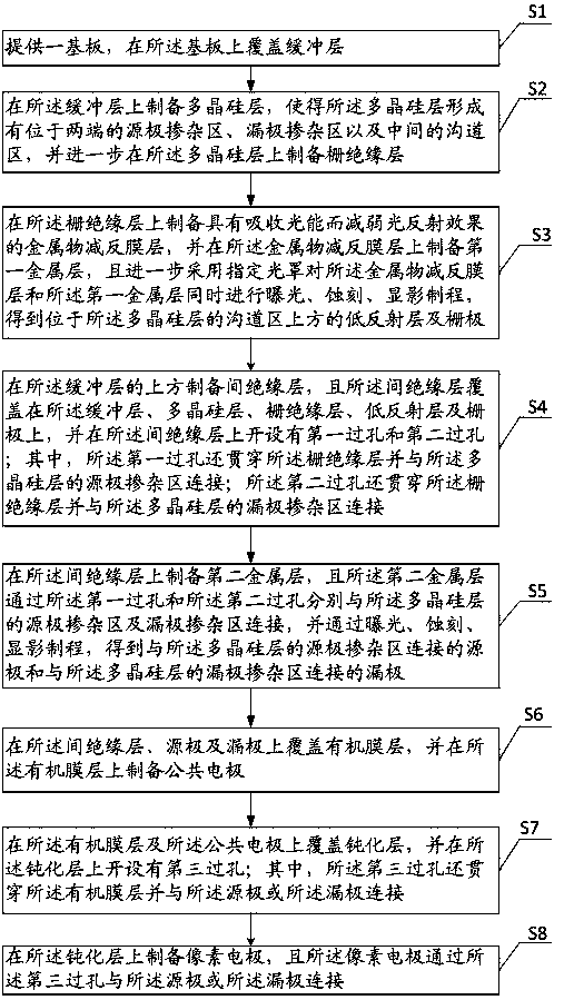
[0043] In order to make the object, technical solution and advantages of the present invention clearer, the present invention will be further described in detail below in conjunction with the accompanying drawings. The directional terms mentioned in the present invention, such as [top], [bottom], [front], [back], [left], [right], [inside], [outside], [side], etc., are only for reference The orientation of the attached schema. Therefore, the directional terms used are used to illustrate and understand the present invention, but not to limit the present invention. In the figures, structurally similar elements are denoted by the same reference numerals.

[0044] Such as figure 1 Shown is a method for preparing an array substrate provided in Embodiment 1 of the present invention, which includes the following steps:

[0045]Step S1, providing a substrate, and covering the buffer layer on the substrate;

[0046] The specific process is to select a transparent substrate made of g...


PUM


Abstract

The invention provides an array substrate, comprising providing a substrate, and sequentially preparing a buffer layer, a polysilicon layer, a gate insulating layer, a low-reflection layer, a gate electrode, an inter-insulating layer, a source-drain electrode, an organic film layer, a common electrode, a passivation layer and a pixel electrode on the substrate; A low-reflective lay and a gate electrode are fabricated by that same mask, and the low-reflective lay has the effect of absorbing light energy and reducing light reflection, replaces the design of a traditional light-shielding metal plate, can also effectively reduce the problem of photogenerated leakage current of an LTPS array substrate structure, and simultaneously saves an original mask manufacture process of the traditional light-shielding metal plate. Therefore, the invention can not only effectively reduce the problem of photogenerated leakage current of the LTPS array substrate structure, but also reduce the number of masks required for manufacturing the array substrate, thereby reducing the production cycle and the cost.

Description

technical field [0001] The invention relates to the technical field of liquid crystal display, in particular to an array substrate and a preparation method thereof. Background technique [0002] Compared with traditional A-Si (Amorphous Silicon Thin Film Transistor) technology, LTPS (Low Temperature Poly-silicon) technology has higher carrier mobility and is widely used in small and medium-sized high-resolution TFT LCDs ( TFT liquid crystal display, Thin Film Transistor liquid crystal display) and AMOLED (active matrix organic light emitting diode, Active-matrix organic light emitting diode) panel production, but the number of photomasks required for the corresponding TFT array substrate production is more More, the product production cycle is longer. Therefore, how to effectively reduce the production cycle of LTPS array substrates, increase production capacity and reduce costs, so as to increase the company's market competitiveness, is currently the focus of the panel ind...

Claims


Application Information

Patent Timeline
Patent Type & Authority Applications(China)
IPC IPC(8): H01L21/84H01L27/12G02F1/1362
CPCG02F1/136209G02F1/136227G02F1/136295H01L27/1214H01L27/1259H01L27/1288
Inventor 陆鹏李立胜颜源
Owner WUHAN CHINA STAR OPTOELECTRONICS TECH CO LTD
Learn More