Pneumatic-electric system of a pneumatic-electric hybrid electric bus

A hybrid power and power battery technology, applied in the field of gas-electric systems, can solve the problems of crowded passengers, small passenger space, and large space occupation, and achieve the effects of good overall stability, reasonable layout, and simple and compact structure.

Pending Publication Date: 2018-12-11
ANHUI ANKAI AUTOMOBILE
View PDF0 Cites 5 Cited by
  • Summary
  • Abstract
  • Description
  • Claims
  • Application Information

AI Technical Summary

Problems solved by technology

[0005] The purpose of the present invention is to solve the unreasonable arrangement and installation of the gas-electric system in the existing gas-electric hybrid bus, the occupied space of the gas-electric system in the gas-electric hybrid bus is very large The structure is not simple and compact enough, there are too many components in the gas-electric system, and the power battery and LNG cylinder in the gas-electric system occupy a large volume, so it is impossible to reserve a large interior space for the whole vehicle, which is not convenient for passenger cars Passengers, the space that passengers can take is small, and passengers are crowded in the bus. The gas-electric system cannot make better use of the frame space in the gas-electric hybrid bus. After the gas-electric system is arranged, the gas-electric hybrid The overall stability of the passenger car is poor, and the safety is also relatively poor, and a gas-electric hybrid bus gas-electric system is proposed

Method used


Image

  • Pneumatic-electric system of a pneumatic-electric hybrid electric bus
  • Pneumatic-electric system of a pneumatic-electric hybrid electric bus

Examples


Embodiment Construction

[0020] The technical solutions of the present invention will be clearly and completely described below in conjunction with the embodiments. Apparently, the described embodiments are only some of the embodiments of the present invention, not all of them. Based on the embodiments of the present invention, all other embodiments obtained by persons of ordinary skill in the art without creative efforts fall within the protection scope of the present invention.

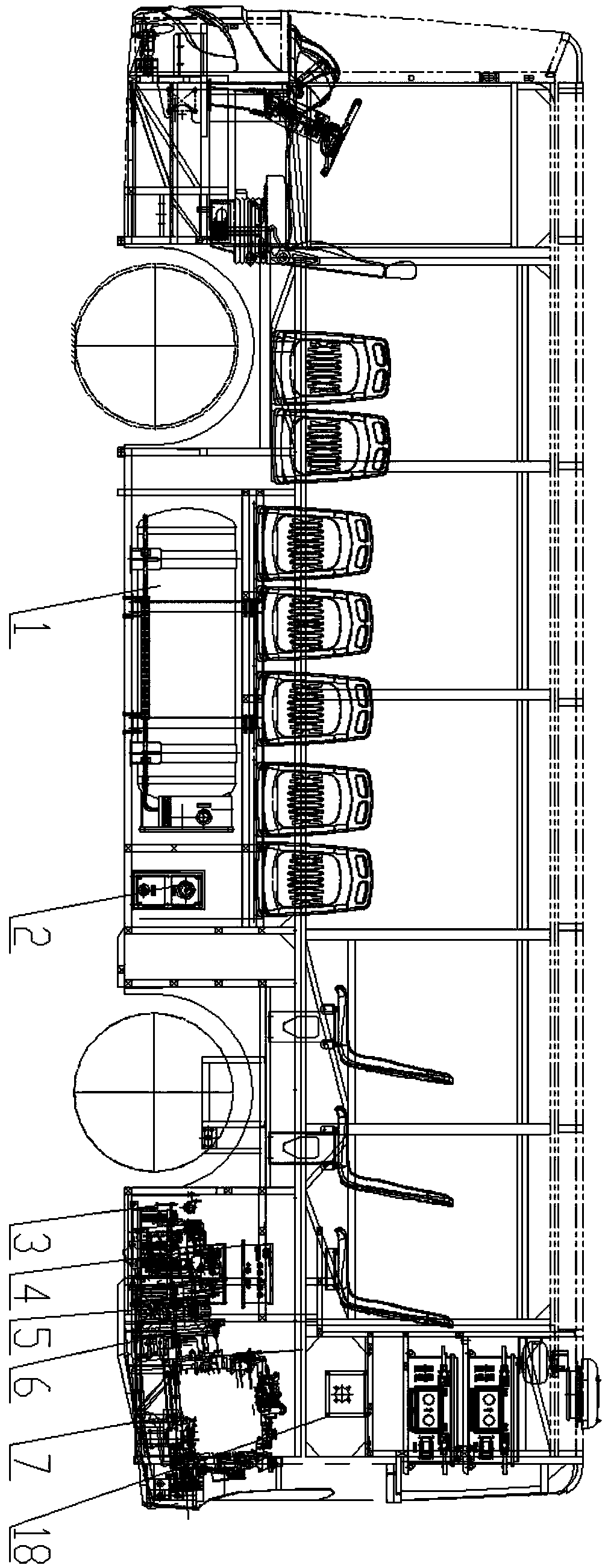
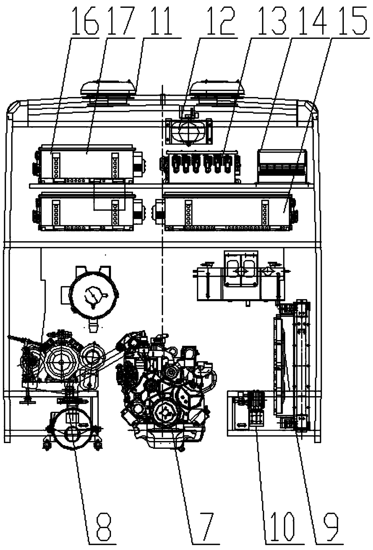
[0021] see Figure 1-2 As shown, a gas-electric hybrid passenger car gas-electric system includes LNG gas cylinder 1, gas control panel 2, generator 7, air-conditioning compressor 8, driving motor circulating water pump 10, high-pressure chamber cooling fan 11, and power battery fire extinguisher 12 and the battery charging port 18, the LNG cylinder 1 is horizontally laid on the left side of the middle section of the vehicle body, and the gas cylinder anti-collision beam is installed between the hatch of the LNG gas cylinde...


PUM


Abstract

The invention discloses a pneumatic-electric system of a pneumatic-electric hybrid electric bus, including LNG cylinders, a gas control panel, an electric generator , an air-conditioning compressor, acirculating water pump for a driving motor, a heat dissipation fan for high-pressure cabin, a power battery fire extinguisher and a battery charging port, The LNG cylinder is horizontally laid on theleft side of the middle section of the body, a cylinder collision beam is installed between the hatch door of the LNG cylinder and the LNG cylinder, the gas control panel is arranged at the rear endof the LNG cylinder, a battery is arranged at the bottom of one end of the system, and the battery is arranged at the bottom of the rear end of the body. The invention has the advantages that: the twohigh-pressure cabin cooling fans are located on the roof directly above the high-pressure cabin, The utility model is used for heat dissipation of the high-pressure cabin, and the power battery fireextinguisher is used for extinguishing the power battery in case of an accident. The system has the advantages of high selectivity, reasonable layout, simple and compact structure, better utilizationof the frame space, and better overall stability and safety performance of the pneumatic-electric hybrid electric bus.

Description

technical field [0001] The invention relates to a gas-electric system, in particular to a gas-electric system for a gas-electric hybrid bus, and belongs to the technical field of application of the gas-electric system for a gas-electric hybrid bus. Background technique [0002] A hybrid vehicle refers to a vehicle whose drive system is composed of two or more single drive systems that can operate simultaneously. Traditional internal combustion engines (diesel or gasoline) and electric motors are used as power sources. [0003] With the rapid development of new energy vehicles, gas-electric hybrid buses are used more and more frequently in daily life. Gas-electric hybrid buses are new types of buses that use natural gas as the engine energy and cooperate with electric motors to jointly drive vehicles. Electric hybrid buses are also It is called a plug-in hybrid electric vehicle. Compared with ordinary hybrid electric vehicles, plug-in hybrid electric vehicles have obvious ad...

Claims


Application Information

Patent Timeline
IPC IPC(8): B60K6/24B60K6/26B60K6/40B60K11/02B60L11/18B60H1/32
CPCB60H1/3204B60K6/24B60K6/26B60K6/40B60K11/02Y02T10/62
Inventor 周剑乔王泽平方维圆刘超司凯江腾
Owner ANHUI ANKAI AUTOMOBILE
Why Eureka
Try Eureka