Numerical control grinding and finishing method for blade shot peening surface

A finishing and grinding technology, used in metal processing equipment, abrasives, manufacturing tools, etc., can solve problems such as small material removal, achieve uniform coverage, avoid overheating, and avoid overcutting.

Active Publication Date: 2018-12-11
AECC AERO SCI & TECH CO LTD
View PDF5 Cites 5 Cited by
  • Summary
  • Abstract
  • Description
  • Claims
  • Application Information

AI Technical Summary

Problems solved by technology

[0003] The purpose of the present invention is to overcome the deficiencies of the existing manual polishing and finishing technology, and provide a numerical control grinding and finishing method for blade shot blasting surface, which can make the surface of the blade shot blasting surface crater under the premise of ensuring that the roughness meets the quality requirements. Uniform coverage, small amount of material removal, and ensure that the stress and influence depth of the shot peening residual compressive stress layer meet the design requirements

Method used


Image

  • Numerical control grinding and finishing method for blade shot peening surface
  • Numerical control grinding and finishing method for blade shot peening surface
  • Numerical control grinding and finishing method for blade shot peening surface

Examples


Embodiment 1

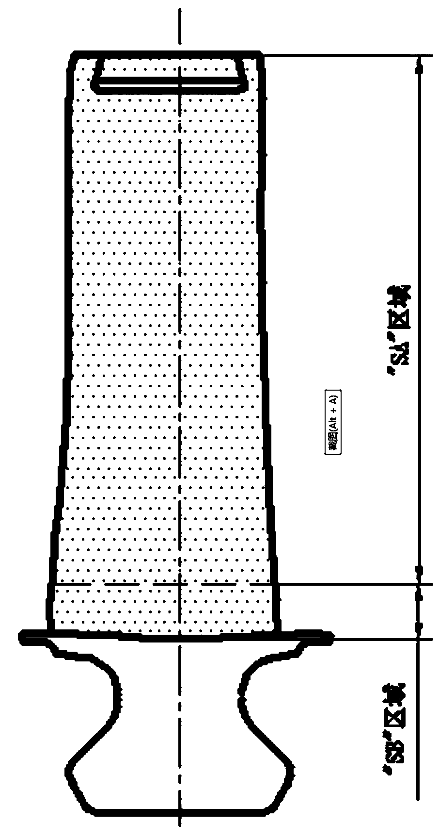
[0038] on a six-coordinate linkage CNC abrasive belt grinder figure 1 The surface of the airfoil in the "SA" region and the shot-peened surface of the blade root fillet transition zone in the "SB" region are ground and finished separately. Through the optimal design of the contact wheel, the selection of finishing tools and cooling methods, as well as the optimization and processing of the program, the research of key grinding parameters such as speed, feed, contact force and step distance can meet different types of blade profiles. Residual compressive stress and roughness design requirements. The specific steps are as follows:

[0039] 1.1 Smoothing the root fillet transition area

[0040] 1.1.1 will be as figure 2 The nylon polishing wheel shown is rounded R2~R3, and installed on the abrasive belt grinder after completion;

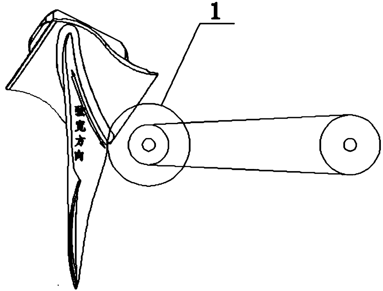
[0041] 1.2.2 If image 3As shown, the nylon wheel 1 reciprocally moves along the chord width direction of the blade shape to smooth the transitio...

Embodiment 2

[0046] on a six-coordinate linkage CNC abrasive belt grinder figure 1 The surface of the airfoil in the "SA" region and the shot-peened surface of the blade root fillet transition zone in the "SB" region are ground and finished separately. Through the optimal design of the contact wheel, the selection of finishing tools and cooling methods, as well as the optimization and processing of the program, the research of key grinding parameters such as speed, feed, contact force and step distance can meet different types of blade profiles. Residual compressive stress and roughness design requirements. The specific steps are as follows:

[0047] 1.1 Smoothing the root fillet transition area

[0048] 1.1.1 will be as figure 2 The nylon polishing wheel shown is rounded R2~R3, and installed on the abrasive belt grinder after completion;

[0049] 1.2.2 If image 3 As shown, the nylon wheel 1 reciprocates along the chord width direction of the blade shape to smooth the transition are...


PUM


Abstract

The invention relates to a numerical control grinding and finishing method for a blade shot peening surface. The numerical control grinding and finishing method for the blade shot peening surface comprises the following steps: finishing a blade root round corner transition zone, coarsely grinding a blade body profile surface, and finely grinding the blade body profile surface. At the same time, aiming at the situation that the blade profile surface is a free-form surface, the curvature changes greatly, and the difference of the sizes and shapes of different blades is large, the numerical control abrasive belt grinding produces the problem of local grinding unevenness. The numerical control grinding and finishing method for the blade shot peening surface provided by the invention optimizesa contact wheel. And for the problem of local less polishing or over polishing, the local treatment is performed through a program. The numerical control grinding and finishing method for the blade shot peening surface provided by the invention has the advantages of uniformly covering a crater on the blade shot peening surface and having small amount of material removal under the premise of ensuring that the roughness meets the quality requirement, and ensuring that the stress and influence depth of a shot peening residual compressive stress layer meet the design requirement.

Description

technical field [0001] The invention relates to the field of blade surface finishing, in particular to a numerical control grinding and finishing method of blade shot peening surface. Background technique [0002] Blades are key parts of aero-engines and gas turbines, and shot peening and surface roughness have an important impact on their fatigue life and aerodynamic efficiency. Shot peening and surface roughness are essentially conflicting design requirements. Shot peening will cause plastic deformation on the surface of the airfoil and form craters with a certain depth. Ra0.25~Ra0.4 after shot peening increases to Ra1.8~2.5 after shot peening, and the design requirement for blade airfoil surface roughness is Ra0.4 or even Ra0.2. The roughness reduction ability of the existing vibrating finishing process is limited. Before vibrating, polyvinyl alcohol polishing wheel or nylon polishing wheel must be used to manually polish the surface of the airfoil shot peening to meet t...

Claims


Application Information

Patent Timeline
Patent Type & Authority Applications(China)
IPC IPC(8): B24C1/10B24C9/00
CPCB24C1/10B24C9/00
Inventor 蒲双龙王照铭雷浩强印灿邓杰李惠李晓彦陈勇刘超
Owner AECC AERO SCI & TECH CO LTD
Why Eureka
Try Eureka