New energy supporting facility

A new energy and facility technology, applied in coupling devices, vehicle connectors, electric vehicles, etc., can solve the problems of easily induced electric shock accidents, inconvenient charging and use, unexpected power failure, etc., to improve stability and safety, and simple structure. , the effect of easy operation

Inactive Publication Date: 2018-12-07
广州同轩信息科技有限公司
View PDF0 Cites 0 Cited by
  • Summary
  • Abstract
  • Description
  • Claims
  • Application Information

AI Technical Summary

Problems solved by technology

Charging piles are supporting facilities for new energy vehicles and are carriers for charging new energy vehicles. However, the traditional charging piles have a single setting mode, and the internal conductive sheets are generally set relatively outside. This conductive sheet is easily damaged by metal sheets or metal rods. Therefore, it is very easy to induce electric shock accidents, and there is a great potential safety hazard. In addition, traditional new energy vehicles have poor stability when charging and connecting, which often causes unexpected power failures, which brings great harm to normal charging. inconvenient

Method used


Image

  • New energy supporting facility
  • New energy supporting facility
  • New energy supporting facility

Examples


Embodiment Construction

[0024] All features disclosed in this specification, or steps in all methods or processes disclosed, may be combined in any manner, except for mutually exclusive features and / or steps.

[0025] Any feature disclosed in this specification (including any appended claims, abstract and drawings), unless expressly stated otherwise, may be replaced by alternative features which are equivalent or serve a similar purpose. That is, unless expressly stated otherwise, each feature is one example only of a series of equivalent or similar features.

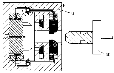
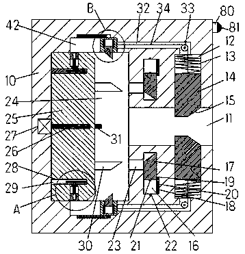
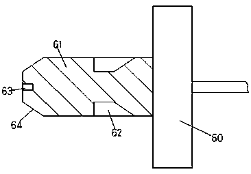
[0026] Such as Figure 1-5As shown, a new energy supporting facility of the device of the present invention includes a charging pile 10 and a charging head 60 connected to a new energy vehicle. The charging head 60 is provided with an insertion cavity 11 with the mouth facing the right, and the insertion cavity 11 The first sliding cavity 12 is symmetrically arranged on the upper and lower inner walls, and the second sliding cavity 24 extendi...


PUM


Abstract

The invention discloses a new energy supporting facility. The new energy supporting facility comprises a charging pile and a charging head which is connected with a new energy vehicle; an insertion chamber with a rightwards-facing opening is formed in the charging head; first slide chambers are symmetrically formed in the upper inner wall and lower inner wall of the insertion chamber; a second slide chamber which extends along a vertical direction and is communicated with the inner wall of the left side of the insertion chamber is formed in the inner wall of the left side of the insertion chamber; locking arms of which the inner side ends extend into the insertion chamber are slidingly installed in the first slide chambers; and a sliding frame is slidingly installed in the second slide chamber; a first screw hole with a leftwards-facing opening is formed in the sliding frame; a first screw rod is installed in the first screw hole in a matched manner; and the left side end of the firstscrew rod is in power connection with a motor fixedly arranged in the inner wall of the left side of the second slide chamber.

Description

technical field [0001] The invention relates to the technical field of new energy vehicles, in particular to a new energy supporting facility. Background technique [0002] New energy vehicles are gradually replacing traditional vehicles with many advantages such as energy saving, environmental protection and pollution-free, and are widely used. Charging piles are supporting facilities for new energy vehicles and are carriers for charging new energy vehicles. However, the traditional charging piles have a single setting mode, and the internal conductive sheets are generally set relatively outside. This conductive sheet is easily damaged by metal sheets or metal rods. Therefore, it is very easy to induce electric shock accidents, and there is a great potential safety hazard. In addition, traditional new energy vehicles have poor stability when charging and connecting, which often causes unexpected power failures, which brings great harm to normal charging. inconvenient. ...

Claims


Application Information

Patent Timeline
IPC IPC(8): H01R13/627H01R13/631H01R13/633H01R13/635H01R13/70B60L11/18
CPCH01R13/6278H01R13/631H01R13/633H01R13/635H01R13/701H01R2201/26
Inventor 林柱坚
Owner 广州同轩信息科技有限公司
Why Eureka
Try Eureka