Irrigation and drainage integrated farmland underground pipe simulation device and method for determining underground pipe combinations

A technology for simulating a device and a hidden pipe, which is applied in the field of agricultural engineering and can solve the problems of time-consuming, laborious drainage of hidden pipes, and complicated methods for determining the buried depth.

Pending Publication Date: 2018-12-07
CHANGCHUN INST OF TECH
View PDF0 Cites 8 Cited by
  • Summary
  • Abstract
  • Description
  • Claims
  • Application Information

AI Technical Summary

Problems solved by technology

[0007] The purpose of the present invention is to propose an irrigation and drainage integrated farmland concealed pipe simulation device and a method for determining the combination of concealed pipes, so as to solve the complex, time-consuming, laborious and unsaturated conditions of farmland existing in the prior art for determining the distance between concealed pipes and buried depth Difficulty in draining underground pipes; determine the optimal spacing and buried depth of irrigation and drainage in underground pipes from the water migration mechanism, and also visually see the soil water migration process from the outside of the box body

Method used


Image

  • Irrigation and drainage integrated farmland underground pipe simulation device and method for determining underground pipe combinations
  • Irrigation and drainage integrated farmland underground pipe simulation device and method for determining underground pipe combinations
  • Irrigation and drainage integrated farmland underground pipe simulation device and method for determining underground pipe combinations

Examples


Embodiment Construction

[0098] Embodiments of the present invention will be further described below in conjunction with the accompanying drawings.

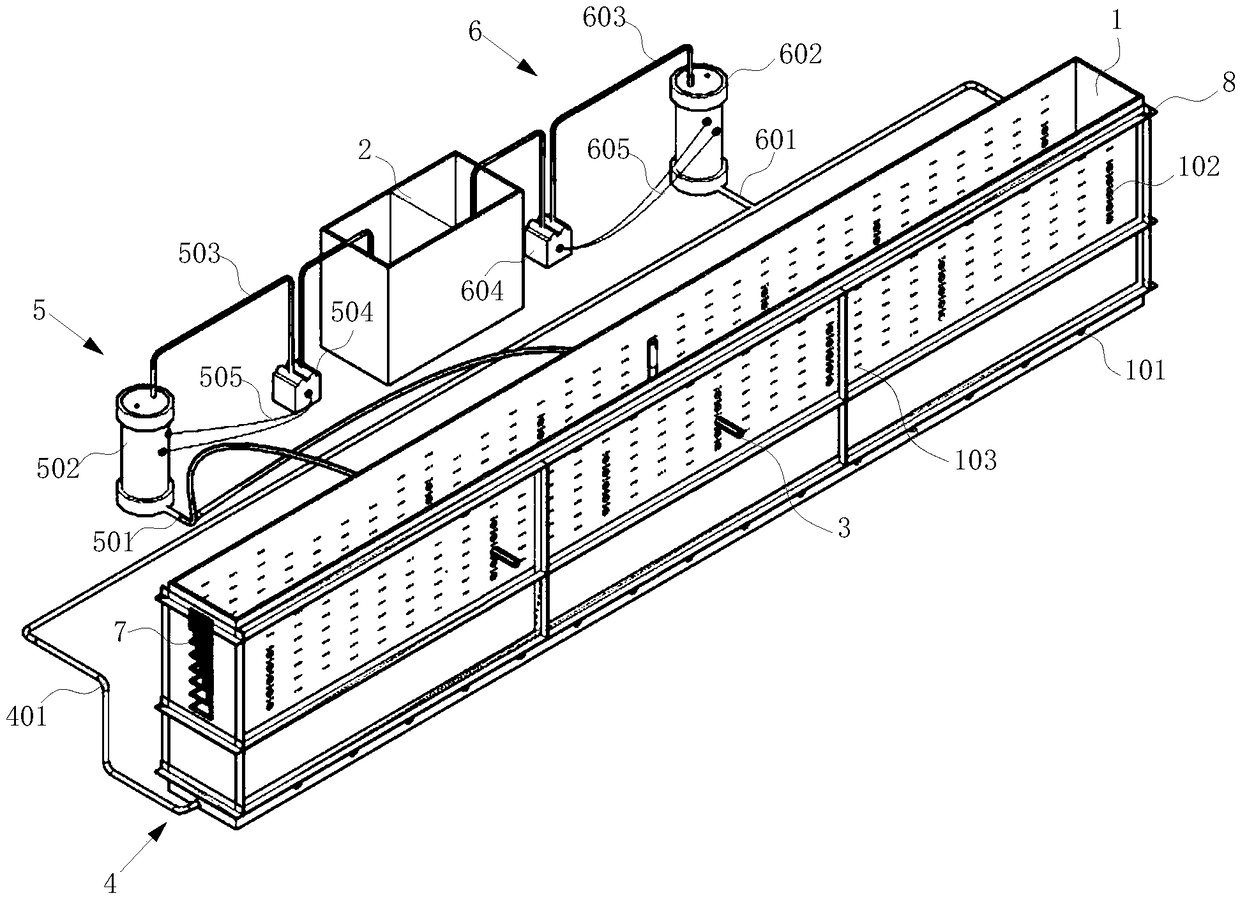
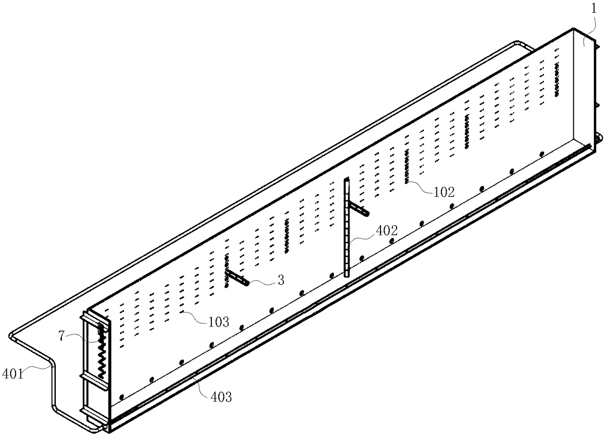
[0099] See attached figure 1 - attached Figure 4 , the irrigation and drainage integrated farmland hidden pipe simulation device of the present invention comprises:

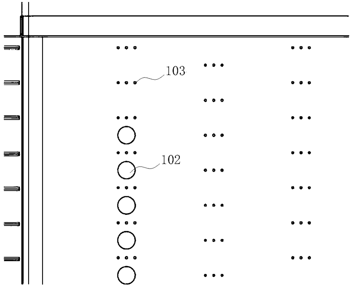
[0100] The box body 1, the box body 1 is a square structure, and a drain hole 101 is opened under the side of the box body 1, and the drain hole 101 communicates with the box body 1, and any two opposite sides of the box body 1 Multiple rows and multiple rows of concealed pipe jacks 102 are relatively arranged, and multiple rows and multiple rows of sensor insertion holes 103 are relatively arranged on any two opposite sides of the box body 1, and two adjacent rows of sensor insertion holes 103 are arranged in a misplaced position;

[0101] Water collection tank 2;

[0102] The plug-in dark pipe 3 or cork that cooperates with the dark pipe jack 102, when the dark pipe jack 102 is idle, ...


PUM

PropertyMeasurementUnit
Faaaaaaaaaa

Abstract

The invention provides an irrigation and drainage integrated farmland underground pipe simulation device and a method for determining underground pipe combinations, and belongs to the technical fieldof agricultural engineering. The irrigation and drainage integrated farmland underground pipe simulation device and the method for determining the underground pipe combinations aim at solving the problems that in the prior art, a method for determining the intervals and the burial depths of underground pipes is complex, time and labor are wasted, and drainage of the underground pipes is difficultunder the farmland unsaturated condition. The simulation device comprises a box body, a water collecting box, inserted type underground pipes or wooden plugs cooperating with underground pipe inserting holes, an underground water simulation structure, air nozzles and seven piezometer tubes. Multiple underground pipe water holes are formed in the portions, located in the box body, of the inserted type underground pipes, one ends of the inserted type underground pipes communicate with the water collecting box through underground pipe water supply units, and the other ends of the inserted type underground pipes communicate with an external collecting facility. The underground water simulation structure communicates with the water collecting box through an underground water supply unit. The air nozzles are arranged at the forming positions of sensor inserting holes formed in the outer surface of the box body. The seven piezometer tubes are arranged at the center axis position of one side face of the box body from top to bottom, form a row and have equal altitude differences.

Description

technical field [0001] The invention belongs to the technical field of agricultural engineering, and in particular relates to an irrigation and drainage integrated farmland concealed pipe simulation device and a method for determining the combination of concealed pipes. Background technique [0002] Underground drainage pipes are widely used in anti-waterlogging areas and saline-alkali land improvement areas because they can effectively control the rise of groundwater, reduce the salinity of groundwater, improve the physical and chemical properties of soil, save land, and increase food production. The spacing and depth of buried pipes restrict the drainage efficiency and economic benefits of the project, and directly affect the popularization and application of plastic concealed pipe drainage and stain reduction technology. The burial depth of the underground pipe is mainly determined by the burial depth of groundwater required to ensure the normal growth of crops, while con...

Claims


Application Information

Patent Timeline
IPC IPC(8): E02B1/02E02B11/00
CPCE02B1/02E02B11/005
Inventor 高金花伊燕平徐阳张礼绍任玉珊
Owner CHANGCHUN INST OF TECH
Why Eureka
Try Eureka