Positioning adjustment mechanism

A positioning adjustment and adjustment mechanism technology, which is applied to metal processing machinery parts, automatic control devices, measuring/indicating equipment, etc., can solve the problems of inability to achieve stop and stop effects, instability, and impact resistance, etc., to facilitate equipment inspection and equipment maintenance, improve the speed of installation and debugging, and the effect of simple structure

Pending Publication Date: 2018-12-07
孙臣慧
View PDF0 Cites 0 Cited by
  • Summary
  • Abstract
  • Description
  • Claims
  • Application Information

AI Technical Summary

Problems solved by technology

[0002] At present, in the adjustment process of equipment and tooling in many fields such as desktop lathes, processing equipment, automation equipment, tooling mechanism positioning, etc., stop, jacking screw, tip, profiling, or measurement while adjusting, there are many automation equipment It is completely adjusted by experience and feel. The problem caused by the above phenomena is that the position is not accurate, and the products produced by different people adjusting the same equipment and the same tooling are not the same, and accurate laser measurement is only a measurement method, which cannot achieve stop. Effects, such as high precision of micrometer, but not resistant to impact and heavy load; products with buffer plus gear stop, whether it is oil pressure buffer or spring buffer, including brands such as festo, smc and srk, cannot be adjusted accurately and record data. It caused a lot of inconvenience and unstable tooling positioning to the equipment adjustment and the people who took over the equipment later.
[0003] In the prior art, micrometer knobs are mostly used, but they are not resistant to pressure shocks in production, and the purchase cost is high

Method used


Image

  • Positioning adjustment mechanism
  • Positioning adjustment mechanism
  • Positioning adjustment mechanism

Examples


Embodiment 1

[0041] combine figure 1 and figure 2As shown, a positioning adjustment mechanism includes a mandrel 1, a rough positioning mechanism 2, a precise positioning mechanism 3 and a buffer force adjustment mechanism 4; the rough positioning mechanism 2 is provided with an axial through hole, and the mandrel 1 and the buffer force The force adjustment mechanism 4 is arranged in the through hole; the precise positioning mechanism 3 is set on the rough positioning mechanism 2, and forms a micrometer-like structure with the rough positioning mechanism 2; the buffer force adjusting mechanism 4 is connected to the above-mentioned mandrel 1 , and is used to buffer the pressure impact of the stop of the target tooling 5.3; the mandrel 1 supports the rough positioning mechanism 2, the rough positioning mechanism 2 roughly sets the stop position of the target tooling 5.3, and the fine positioning mechanism 3 is further finely adjusted The target tooling 5.3 stop position; thus, the position...

Embodiment 2

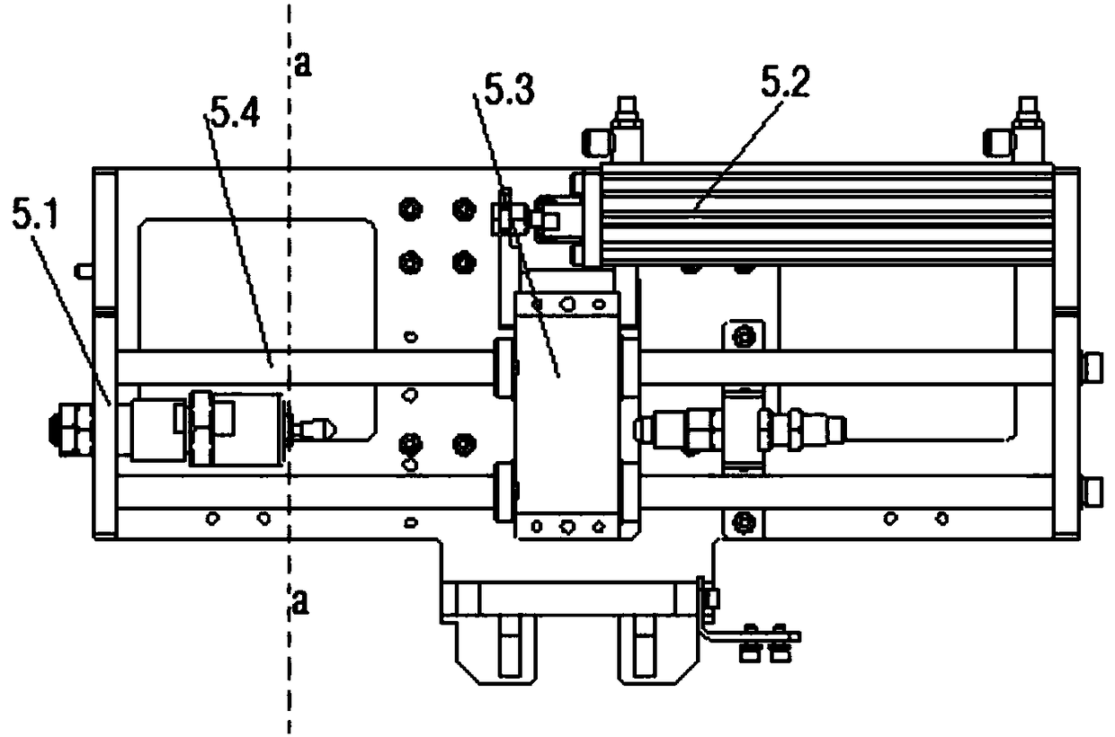
[0051] to combine image 3 As shown in the specific usage of the positioning adjustment mechanism of the present invention, embodiment 2 shows a specific working process of the coarse positioning adjustment mechanism of the present invention as follows: in embodiment 2, according to actual production needs, the target tooling 5.3 is driven by the cylinder 5.2 Moving on the screw rod 5.4, the positioning adjustment mechanism is fixed on the stop block 5.1; the positioning adjustment mechanism cooperates with the coarse positioning sleeve 2.1 in the coarse positioning mechanism 2 and the coarse positioning lock nut 2.2, and the approximate position where the target tooling 5.3 stops is roughly predetermined. as attached image 3 In the position a shown, the cylinder 5.2 drives the target tooling 5.3 to slide on the screw rod 5.4, and the left side contacts the buffer head 4.1, guided by the mandrel 1, and transmits the pressure of the target tooling 5.3 to the buffer spring 4.2,...


PUM


Abstract

The invention provides a positioning adjustment mechanism and relates to the field of machining. The positioning adjustment mechanism comprises a mandrel, a coarse positioning mechanism and a precisepositioning mechanism, wherein the coarse positioning mechanism is provided with an axial through hole, and the mandrel and a buffer force adjusting mechanism are arranged in the through hole; the precise positioning mechanism is installed on the coarse positioning mechanism in a sleeving mode and forms a micrometer-like structure together with the coarse positioning mechanism; the buffer force adjusting mechanism is connected with the mandrel and used for buffering pressure impact caused by stop of a target tool; and the coarse positioning mechanism roughly presets the forwarding or stop position of the target tool, and the precise positioning mechanism further adjusts the position of the target tool precisely by precisely positioning and adjusting differential motion of a thread on a dial according to the position of the coarse positioning mechanism. The positioning adjustment mechanism is simple in structure and convenient to operate, impact pressure of loads is effectively buffered, and in the process that the target tool is stopped and positioned, precise positioning and accurate reading are achieved.

Description

technical field [0001] The invention relates to the field of mechanical processing, in particular to a precise positioning adjustment mechanism capable of recording numerical values. Background technique [0002] At present, in the adjustment process of equipment and tooling in many fields such as desktop lathes, processing equipment, automation equipment, tooling mechanism positioning, etc., stop, jacking screw, tip, profiling, or measurement while adjusting, there are many automation equipment It is completely adjusted by experience and feel. The problem caused by the above phenomena is that the position is not accurate, and the products produced by different people adjusting the same equipment and the same tooling are not the same, and accurate laser measurement is only a measurement method, which cannot achieve stop. Effects, such as high precision of micrometer, but not resistant to impact and heavy load; products with buffer plus gear stop, whether it is oil pressure b...

Claims


Application Information

Patent Timeline
Patent Type & Authority Applications(China)
IPC IPC(8): B23Q17/22B23Q15/14
CPCB23Q17/22B23Q15/14
Inventor 孙臣慧
Owner 孙臣慧
Why Eureka
Try Eureka