Left aurcle plugging device with closed ring structure and assembly method of left aurcle plugging device

An occluder and closed-loop technology, which is applied in the field of medical devices, can solve the problems of increasing the overall length, hanging, and increasing the diameter of the sheath, so as to ensure the sealing effect, improve the sealing performance, and reduce the effect of residual shunt

Pending Publication Date: 2018-12-04
HANGZHOU NUOMAO MEDTECH CO LTD
View PDF0 Cites 1 Cited by
  • Summary
  • Abstract
  • Description
  • Claims
  • Application Information

AI Technical Summary

Problems solved by technology

If the sealing part cannot fit tightly with the left atrial appendage, it may cause the sealing part to hang in the left atrium, which cannot effectively block the opening of the left atrial appendage, and may further increase the risk of thrombosis
One of the main factors causing the sealing part to not be effectively attached to the left atrial appendage is related to the connection mode between the sealing part and the anchoring part, that is, the anchoring part and the sealing part cannot be tightly connected together, and the product The overall length of the product is longer, and the anchoring part is radially compressed after release, which further increases the overall length of the product after release. At the same time, it can cause the axial distance between the sealing part and the anchoring part to increase, and the sealing part cannot be effectively attached to the product after it is released. Left atrial appendage ostium, causing residual shunt
[0005] In the existing left atrial appendage occluder with double-disc structure, the structure of the anchoring part is generally braided to form a mesh structure, and cut to form a rod shape. For the anchoring part of the braided mesh structure, due to the fact that the wires used in the braiding process will partially cross Therefore, the size of the delivery sheath required for the anchoring part of the braided mesh structure is often larger than that of the cutting structure under the same conditions; while the cutting rod-shaped anchoring part, because the ends of the rod-shaped structure are relatively spaced and suspended, After it is retracted into the sheath, and then pushed out again, there is a risk that the end of the support body is easy to kink, which leads to the failure of normal deployment of the anchoring part. Increasing the covering will increase the diameter of the sheath used

Method used


Image

  • Left aurcle plugging device with closed ring structure and assembly method of left aurcle plugging device
  • Left aurcle plugging device with closed ring structure and assembly method of left aurcle plugging device
  • Left aurcle plugging device with closed ring structure and assembly method of left aurcle plugging device

Examples


Embodiment 1

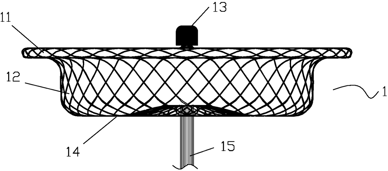
[0160] Such as figure 1 As shown, the sealing part 1 of the left atrial appendage occluder of the present invention is braided with nickel-titanium wire. The sealing part 1 includes a disk surface 11, a waist 12 and a disk bottom 14. There is a plug head 13 at the end of the disk surface for connecting the delivery device. The sealing part 1 is a cage-shaped structure with a certain internal space as a whole. In the predetermined state, the waist 12 is roughly cylindrical, and a layer of flow-resistant film is respectively sewn in the middle area of ​​the disk surface 11, the waist 12, and the bottom 14 of the disk. (omitted in the figure).

[0161] Before the sealing part 1 and the anchoring part 2 are connected, they are shaped by high-temperature heat treatment of the mould, and the sealed part 1 after heat treatment and shaped has a nickel-titanium wire 15 with a distal constriction treatment.

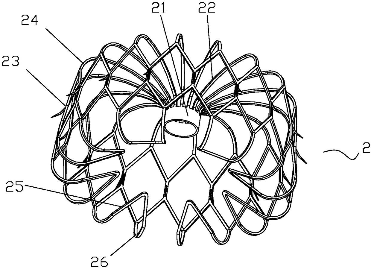
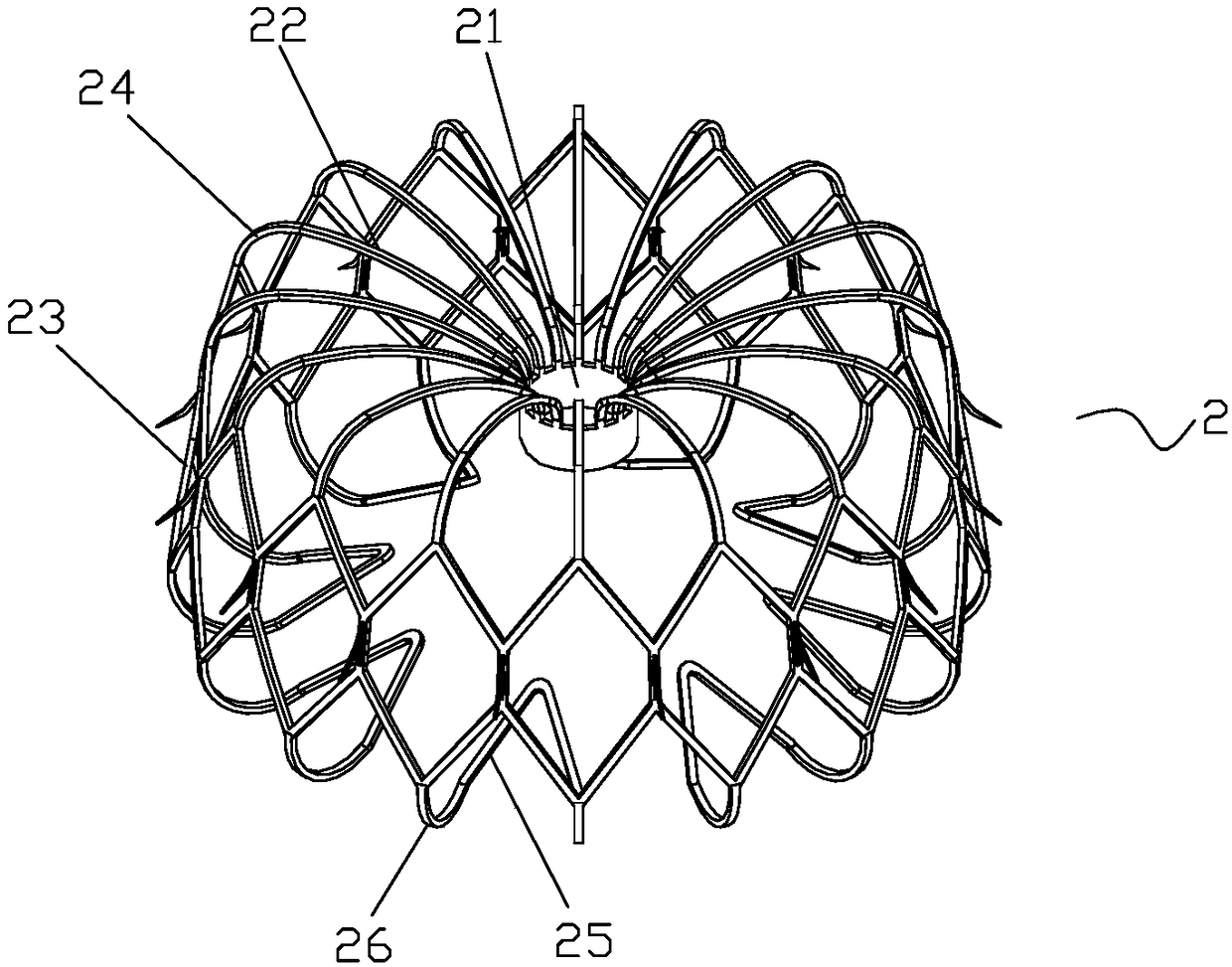
[0162] Such as Figure 2a ~ Figure 2b As shown, the anchoring part 2 is form...

Embodiment 2

[0186] see Figure 5 , The difference between this embodiment and Embodiment 1 is only the shape of the sealing part 1, the sealing part is an inverted cone, and one or two layers of flow-blocking films are arranged inside, and the middle part of the side of the sealing part facing the anchor part faces the anchor One side of the part protrudes, and is tightly pressed against the anchor part through the tapered part.

Embodiment 3

[0188] see Image 6 , the difference between this embodiment and embodiment 1 is only the shape of the sealing part 1, the sealing part 1 is a flat disk, that is, the sealing disk, the sealing disk is a double-layer structure, and a flow-blocking film is arranged inside, under the effect of the pre-tightening force Next, the side of the sealing part facing the anchoring part is pressed against the anchoring part.

[0189] Description of release process

[0190] see Figure 7a ~ Figure 7d ,as well as Figure 8a ~ Figure 8d , taking the left atrial appendage occluder of embodiment 3 as an example, the release process is that the left atrial appendage occluder is connected to the operating handle through a steel cable 5, and a sheath tube 6 is provided on the outer sliding sleeve of the steel cable 5, and the left atrial appendage is sealed. The occluder is also accommodated in the sheath tube 6 after being compressed.

[0191]The left atrial appendage occluder passes through...


PUM


Abstract

The invention discloses a left aurcle plugging device with a closed ring structure and an assembly method of the left aurcle plugging device. The left aurcle plugging device comprises a sealing part and an anchoring part which are connected with each other, wherein the sealing part and the anchoring part abut against each other, the anchoring part is formed through cutting, and before release, thefar-end side of the anchoring part is of a closed ring structure. For the left aurcle plugging device, the shape of the tail end (the end far away from the sealing part before release) of the anchoring part is improved, so that the twisting of the tail end is prevented, and the release of a plurality of times is facilitated. Further, the connecting mode of the sealing part and the anchoring partis also improved, so that the integral axial elongation of the left aurcle plugging device can be avoided and delayed, and further, the sealing part attaches to and plugs the left aurcle opening.

Description

technical field [0001] The invention relates to a medical device, in particular to an interventional treatment device for blocking the left atrial appendage. Background technique [0002] Atrial fibrillation (abbreviated as atrial fibrillation) is the most common sustained cardiac arrhythmia. The incidence of atrial fibrillation continues to increase with age, up to 10% of people over the age of 75. During atrial fibrillation, the frequency of atrial excitation reaches 300-600 beats per minute, the heartbeat frequency is often fast and irregular, and the atrium loses effective systolic function. In atrial fibrillation, the contractility of the left atrial appendage decreases, coupled with the shape characteristics of the left atrial appendage itself and the unevenness of the muscle trabeculae in the left atrial appendage, which makes the blood flow in the left atrial appendage vortex and slows down, which promotes the formation of thrombus. More than 90% of left atrial thr...

Claims


Application Information

Patent Timeline
IPC IPC(8): A61B17/12
CPCA61B17/12109A61B17/12122A61B17/12168A61B17/12172A61B17/12177A61B2017/00477A61B2017/00243A61B2017/00526A61B2017/00867A61B2017/1205A61B2017/12054
Inventor 王永胜李建民丘家明
Owner HANGZHOU NUOMAO MEDTECH CO LTD
Why Eureka
Try Eureka