Three-color laser light source and laser projection television

A technology of laser light sources and laser beams, which is applied in optics, instruments, projection devices, etc., can solve the problems of large volume and complex structure of laser light sources, and achieve the effect of small volume, simple optical path and few optical components

Active Publication Date: 2018-11-30
QINGDAO HISENSE LASER DISPLAY CO LTD
View PDF7 Cites 3 Cited by
  • Summary
  • Abstract
  • Description
  • Claims
  • Application Information

AI Technical Summary

Problems solved by technology

[0006] The invention provides a three-color laser light source for laser TV, which can solve the problems of complex structure and large volume of the existing laser light source

Method used


Image

  • Three-color laser light source and laser projection television
  • Three-color laser light source and laser projection television
  • Three-color laser light source and laser projection television

Examples


Embodiment 1

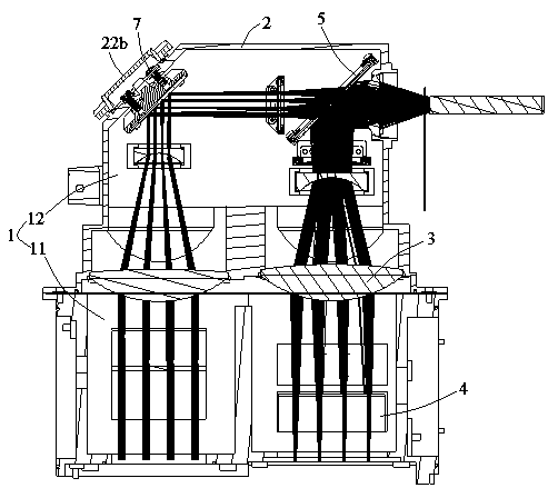
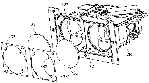
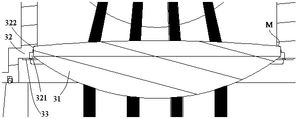
[0031] figure 1 and figure 2 It is a specific embodiment of the three-color laser light source of the laser TV in the embodiment of the present invention. The three-color laser light source of the laser TV in this embodiment includes a housing 2 with a cavity 1 inside, and the inner wall of the cavity 1 faces inwardly. Extending and protruding to form an inner wall extension 32, the first chamber 11 contains a laser assembly 4 and a first light-combining lens (not shown due to beam blocking), the laser assembly 4 includes blue lasers, red lasers and green lasers, the first The light-combining lens receives the laser beams emitted by the laser components and combines the beams for output.

[0032] The second chamber 12 accommodates a second optical lens assembly 5, which is used to shape the laser beams and combine them into one output from the light outlet of the casing. The laser beam emitted by the first light-combining lens is incident on the narrowing lens 31 and the se...

Embodiment 2

[0063] An embodiment of the present invention provides a laser projection television, such as Figure 10As shown, it includes a laser light source 10, an optical machine 20, and a lens 30. The laser light source 10 provides illumination for the optical machine 20. The optical machine 20 modulates the light beam and outputs it to the lens 30 for imaging, and finally projects it to a projection medium 40 such as a screen. Or display pictures on the wall. Specifically, the lens 30 is an ultra-short-focus lens, and the laser projection television is an ultra-short-focus projection device. Wherein, the laser light source in this embodiment can be the laser light source of the above-mentioned embodiment 1, and the same content components will not be described again. The laser projection device in the embodiment of the present invention uses a three-color laser light source, which can make full use of the high brightness of the laser light source itself. The advantages of wide color...


PUM


Abstract

The invention discloses a three-color laser light source which comprises a shell. A first cavity and a second cavity are arranged in the shell, and the first cavity contains a laser assembly and a first light composition lens. The laser assembly comprises a blue laser, a red laser and a yellow laser. The first light composition lens receives laser beams emitted by the laser assembly, combines thebeams and then outputs the beams. The second cavity contains a second optical lens assembly, and the second optical lens assembly is used for shaping the laser beams and finally combines the laser beams into one path of laser beams to be output from a light outlet of the shell. The laser beams emitted from the first light composition lens are sequentially incident to a beam shrinkage lens and thesecond optical lens assembly. The inner wall of the shell extends to define a mounting window, and the beam shrinkage lens is arranged in the mounting window. The beam shrinkage lens and the inner wall extending part of the shell divide the first cavity and the second cavity into two cavities which are not in communication. The three-color laser light source provided by the invention can achieve highlight and wide color gamuts, and meanwhile a light source light path is compact so as to be beneficial to miniaturization of the size.

Description

technical field [0001] The invention relates to the technical field of laser televisions, in particular to a three-color laser light source for laser televisions. Background technique [0002] Laser is a light source with high brightness, strong directionality, and monochromatic coherent light beam. Due to its many advantages, it has been gradually used as a light source in the field of projection display technology in recent years. [0003] At present, laser TV is mainly composed of optical engine, heat dissipation system, and circuit control system; its core component is the optical engine. The optical engine part is composed of a light source part and an optical machine part. The function of the light source part is to provide illumination for the light machine, and the function of the light machine part is to modulate the illumination beam provided by the light source, and finally form a projection image through the lens. [0004] The light source part of a laser TV usu...

Claims


Application Information

Patent Timeline
Patent Type & Authority Applications(China)
IPC IPC(8): G03B21/20
CPCG03B21/20G03B21/2013G03B21/2033G03B21/206G03B21/208
Inventor 李建军
Owner QINGDAO HISENSE LASER DISPLAY CO LTD
Why Eureka
Try Eureka