
Air mixing treatment system for flue gas

A treatment system and air mixing technology, applied in the field of flue gas treatment, can solve the problems of large volume of air mixing chamber and too long pre-mixing air pipeline

Pending Publication Date: 2018-11-30
HUBEI JINLU ENERGY SAVING LTD CO
View PDF0 Cites 1 Cited by
  • Summary
  • Abstract
  • Description
  • Claims
  • Application Information

AI Technical Summary

Problems solved by technology

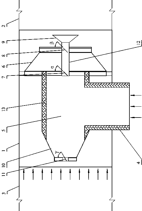
[0003] The main purpose of the present invention is to propose a flue gas mixed air treatment system, aiming at solving the problems of too long premixed air pipes or too large volume of the mixed air chamber in the existing flue gas mixed air treatment, and providing a flue gas mixed air Uniform, good air mixing effect, compact structure, small footprint, low cost flue gas mixing air treatment system

Method used


Image

  • Air mixing treatment system for flue gas
  • Air mixing treatment system for flue gas
  • Air mixing treatment system for flue gas

Examples


Embodiment Construction

[0024] It should be noted that if there are directional indications (such as up, down, left, right, front, back...) in the embodiment of the present invention, the directional indications are only used to explain how to move in a certain posture (as shown in the accompanying drawings). If the specific posture changes, the directional indication will also change accordingly.

[0025] In addition, if there are descriptions involving "first", "second" and so on in the embodiments of the present invention, the descriptions of "first", "second" and so on are only for descriptive purposes, and should not be interpreted as indicating or implying Its relative importance or implicitly indicates the number of technical features indicated.

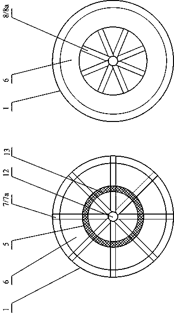
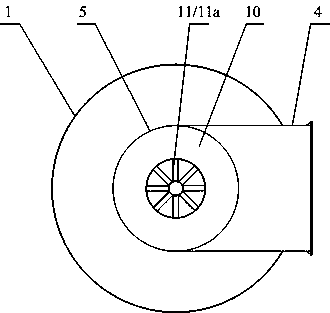
[0026] The present invention proposes a flue gas mixing air treatment system, Figure 1 to Figure 4 It is an embodiment of the flue gas mixed air treatment system proposed by the present invention.

[0027] Please also refer to Figure 1 to Figure...


PUM


Abstract

The invention discloses an air mixing treatment system for flue gas. The air mixing treatment system comprises an air mixing pipe, an air outlet pipe, a tail gas delivery pipe and a high-temperature flue gas delivery pipe, and further comprises an air mixing treatment device arranged in the air mixing pipe; the air mixing treatment device comprises an air pre-mixing pipe and an air final mixing pipe; the air pre-mixing pipe is arranged a hollow cavity in an air mixing chamber; the high-temperature flue gas delivery pipe is hermetically connected with the side wall of the air pre-mixing pipe and penetrates through an inner cavity of the air pre-mixing pipe; the air final mixing pipe is connected with an air outlet of the air pre-mixing pipe; an air inlet of the air final mixing pipe is greater than the air outlet of the air pre-mixing pipe; and the air final mixing pipe is a tapered pipe arranged in manner of gradually reducing from the air inlet end to the air outlet end of the air final mixing pipe. According to the technical solution of air mixing treatment system disclosed by the invention, intensive mass transfer and heat transfer mixing is performed on high-temperature flue gas and tail gas entering the air pre-mixing pipe and the air final mixing pipe, so that the high-temperature flue gas and the tail gas are exchanged more fully in heat, and mixed more evenly, and a heat transfer and mass transfer effect is better.

Description

technical field [0001] The invention relates to the technical field of flue gas treatment, in particular to a flue gas mixed air treatment system. Background technique [0002] The tail flue gas generated in the processing and production needs to be discharged after the flue gas denitrification treatment to avoid polluting the environment. The tail flue gas denitrification treatment usually requires supplementary combustion of high-temperature flue gas and tail gas mixed air treatment, flue gas at various temperatures Convergence in the main pipeline usually requires a pipeline length of about 10×D (D: pipeline diameter), and the temperature field distribution on its radial section can meet the requirements for use. There are usually two ways to deal with it. One is to directly connect the pipes to extend the length of the main pipe to meet the use requirements; the other is to make a mixed air chamber to prolong the mass transfer and heat transfer time of the flue gas by re...

Claims


Application Information

Patent Timeline
IPC IPC(8): F23J15/06F23J15/02
CPCF23J15/02F23J15/06Y02E20/30
Inventor 黄萌龚旭徐顺双
Owner HUBEI JINLU ENERGY SAVING LTD CO
Learn More