Flue gas treatment system and method after incineration of hazardous wastes

A flue gas treatment system and hazardous waste technology, applied in the field of flue gas treatment, can solve the problems of large system resistance, increase of auxiliary fuel, high treatment cost, etc., reduce investment cost and operation cost, reduce floor area, and reduce treatment cost Effect

Pending Publication Date: 2018-11-30
江苏绿景环保设备有限公司
View PDF6 Cites 3 Cited by
  • Summary
  • Abstract
  • Description
  • Claims
  • Application Information

AI Technical Summary

Problems solved by technology

[0008] The above-mentioned process has the following disadvantages: (1) The process flow is long; the system resistance is large; the power consumption of the selected induced draft fan is increased by at least 20%; (2) the low-temperature saturated flue gas produced by wet deacidification requires flue gas reheating In order to enter the SCR denitrification reactor for deep denitrification treatment; when the flue gas is reheated, energy consumption such as auxiliary fuel needs to be increased; (3) the wet deacidification tower used for the deep deacidification of the flue gas produces salty wastewater during the deacidification process; Its salty wastewater has a high salt content; it cannot be directly treated by water for biochemical treatment; most enterprises currently use three-effect evaporators to evaporate and crystallize salty wastewater, and the treatment cost is high
(4) Excessive lime can be sprayed into the dry deacidification tower to make the deacidification efficiency reach 65%-75%; the lime utilization efficiency is not high, the amount of fly ash produced increases and the landfill cost increases

Method used


Image

  • Flue gas treatment system and method after incineration of hazardous wastes

Examples


Embodiment 1

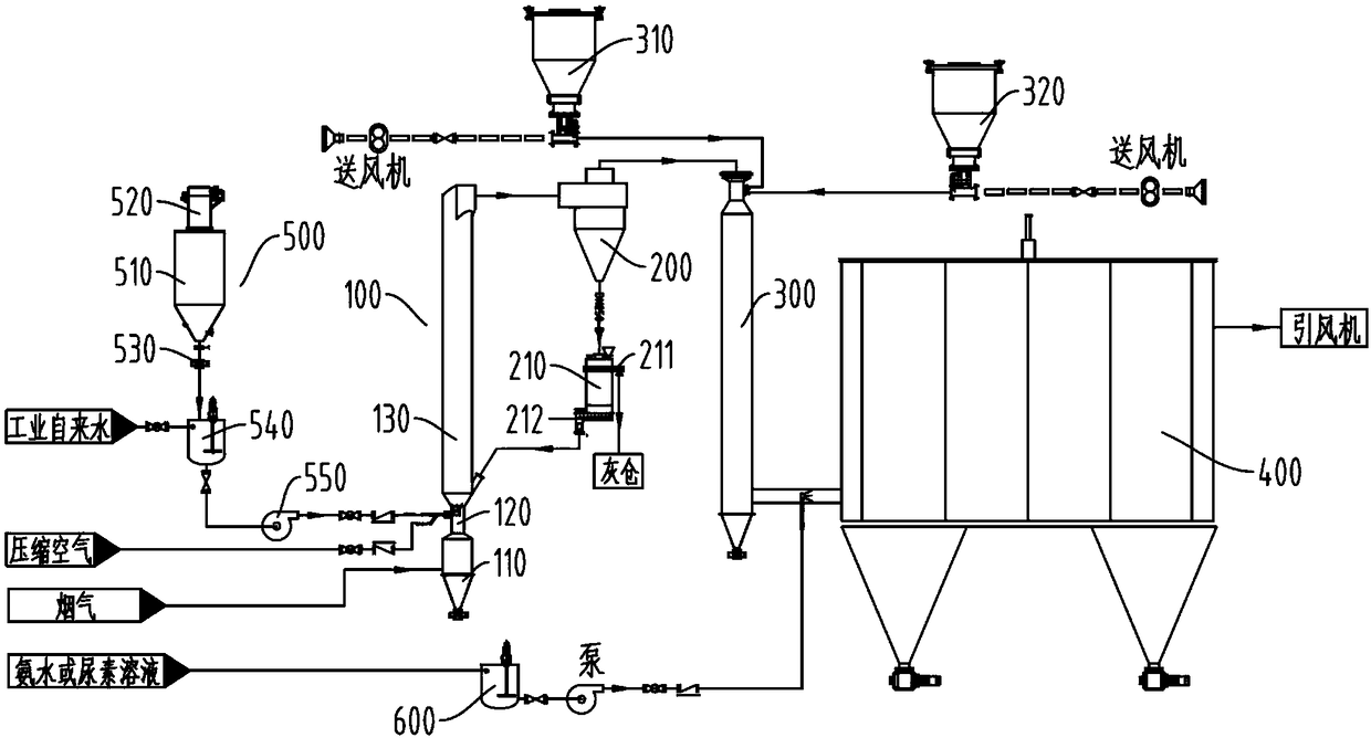
[0035] Such as figure 1 As shown, Embodiment 1 of the present invention provides a flue gas treatment system after hazardous waste incineration, including a semi-dry deacidification tower 100, a cyclone dust collector 200, a dry deacidification tower 300, ceramic Fiber filter tube dedusting reactor 400 and induced draft fan: wherein, the top of the semi-dry type deacidification tower 100 communicates with one side of the cyclone dust collector 200, and the top of the cyclone dust collector 200 communicates with the top of the dry type deacidification tower 300, dry The lower side of the deacidification tower 300 communicates with the lower side of the ceramic fiber filter tube dust removal reactor 400, and the upper side of the ceramic fiber filter tube dust removal reactor 400 is connected with the induced draft fan; the semi-dry deacidification tower 100 is also connected with The lime slurry preparation system 500, the top of the dry deacidification tower 300 is also connec...

Embodiment 2

[0050] According to the system for treating flue gas after incineration of hazardous waste provided in Embodiment 1, this embodiment 2 provides a method for treating flue gas after incineration of hazardous waste, including the following steps:

[0051] S1: The lime slurry preparation system is used to prepare lime slurry. The flue gas from the incineration of hazardous waste enters from the bottom of the semi-dry deacidification tower 100 through the pipeline and reacts with the lime slurry pumped into the bottom of the semi-dry deacidification tower 100. The removal efficiency of sulfur dioxide and HCl in the gas reaches more than 90%;

[0052] S2: The flue gas treated by the semi-dry deacidification tower 100 enters the cyclone dust collector 200 from the top of the semi-dry deacidification tower 100 for treatment, and 90-99% of the dust and inert carrier particles in the flue gas are separated ;

[0053] S3: The flue gas enters from the top of the dry-type deacidification...


PUM

PropertyMeasurementUnit
denitrification rateaaaaaaaaaa

Abstract

The invention discloses a flue gas treatment system and method after incineration of hazardous wastes. The system comprises a semi-dry deacidification tower, a cyclone dust collector, a dry deacidification tower, a ceramic fiber filter tube dedusting reactor and an induced draft fan and the above units are orderly connected through pipes. The top of the semi-dry deacidification tower is communicated with one side of the cyclone dust collector. The top of the cyclone dust collector is communicated with the top of the semi-dry deacidification tower. The lower side of the dry deacidification tower is communicated with the lower side of the ceramic fiber filter tube dedusting reactor. The upper side of the ceramic fiber filter tube dedusting reactor is connected to the induced draft fan. The semi-dry deacidification tower is connected to a lime slurry preparation system. The top of the dry deacidification tower is respectively connected to a baking soda bin and an activated carbon bin. Thejoint of the dry deacidification tower and the ceramic fiber filter tube dedusting reactor is connected to an ammonia water tank or a urea tank. The system can effectively reduce the cost and energyconsumption of the flue gas treatment and has high flue gas treatment efficiency.

Description

technical field [0001] The invention relates to the technical field of flue gas treatment, in particular to a system and method for treating flue gas after incineration of hazardous waste. Background technique [0002] In the environmental industry, due to its own characteristics, the incineration and disposal of hazardous waste requires extremely high technical requirements in the processing process, which requires the close cooperation of chemical engineering, combustion technology, automation technology and information technology. Hazardous waste contains a large amount of organic matter and nitrogen, sulfur, phosphorus and halogen elements, which will produce dioxin, dust and SO during incineration 2 , HCl, HF, NO, NO 2 and other acidic gases (hereinafter collectively referred to as flue gas), in order to remove these toxic gases from the flue gas before discharge, flue gas purification treatment is required, and it is necessary to ensure that the entire disposal proces...

Claims


Application Information

Patent Timeline
Patent Type & Authority Applications(China)
IPC IPC(8): B01D53/86B01D53/83B01D53/78B01D53/68B01D53/50B01D53/56B01D50/00
CPCB01D53/50B01D53/68B01D53/685B01D53/78B01D53/83B01D53/8625B01D2258/0291B01D50/60
Inventor 周亦军李晓东周述华陈开成
Owner 江苏绿景环保设备有限公司
Why Eureka
Try Eureka