
Quick-clamping flow-stabilizing locking connection section for petroleum pipeline

A technology for clamping, steady-flow locking, and oil pipelines. It is used in threaded connections, pipes/pipe joints/fittings, and pipe components. It can solve problems such as reduced sealing, reduced local pipeline strength, and oil leakage. Invasive corrosion damage, avoiding structural corrosion damage, preventing internal and external flow leakage

Pending Publication Date: 2018-11-27
BAOJI CHUANGXIN METAL MATERIALS
View PDF9 Cites 0 Cited by
  • Summary
  • Abstract
  • Description
  • Claims
  • Application Information

AI Technical Summary

Problems solved by technology

[0004] The above challenges cannot be avoided by using locking joints to connect pipelines. Specifically, the locking joints at the joints of pipelines in the prior art usually have radius constriction sections or pipe diameter steps in order to enhance the sealing performance.
When the diameter of the pipe suddenly increases, it will cause a sudden pressure drop in the incoming flow. In a relatively vacuum area, the pressure is low, and the volatile substances in the oil will be partially volatilized, which directly affects the inner wall of the oil pipeline connection. In severe cases , it will further affect the contact area of ​​different components at the oil management joint with the air, causing local corrosion damage, long-term accumulation will lead to a decrease in sealing performance, and even oil leakage; and when the pipe diameter suddenly becomes smaller, the local pressure increases , the flow rate increases, and the impact force of the petroleum medium on the pipe wall increases, especially when the distance from the pressurization or heating base station is close, after the impact force of petroleum on the pipe wall causes damage to the oxide layer of the metal pipe wall, the acidity in it will Corrosive components will further damage the exposed metal, and will accumulate serious structural damage for a long time, greatly reducing the strength of local pipelines

Method used


Image

  • Quick-clamping flow-stabilizing locking connection section for petroleum pipeline
  • Quick-clamping flow-stabilizing locking connection section for petroleum pipeline
  • Quick-clamping flow-stabilizing locking connection section for petroleum pipeline

Examples


Embodiment Construction

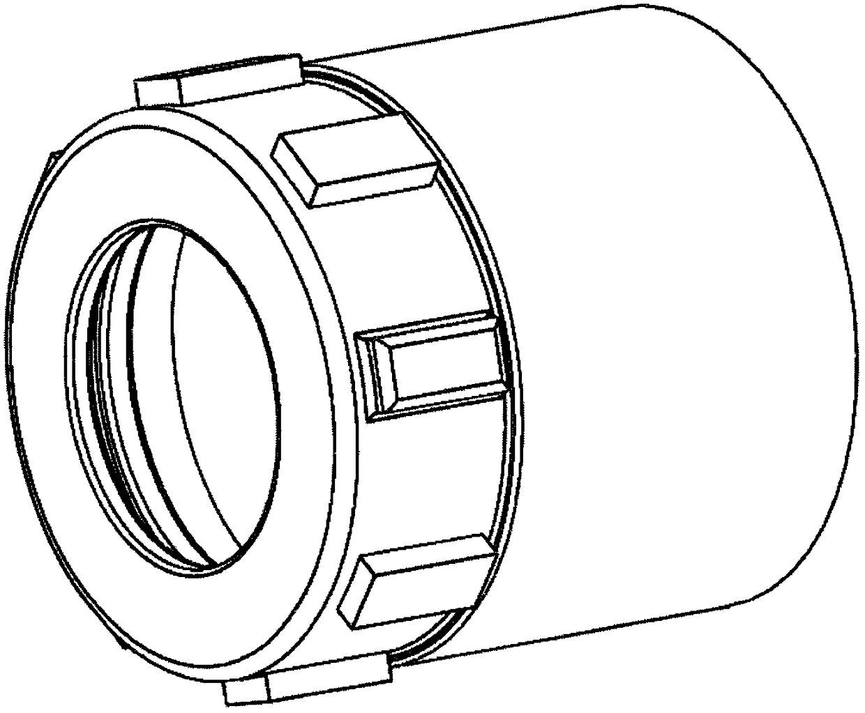
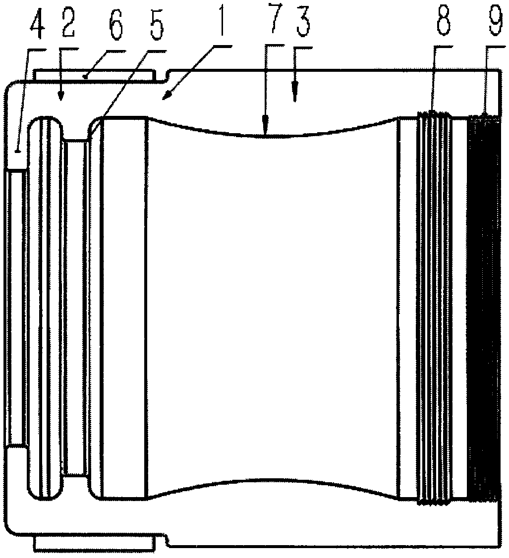
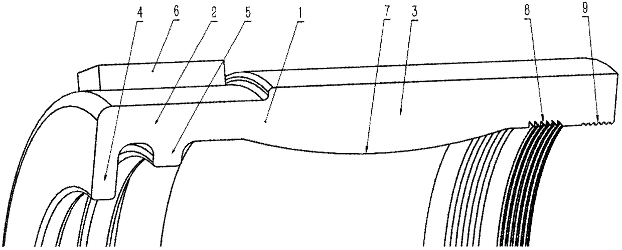
[0033] Below you can refer to the attached Figure 1-6 And the content of the text to understand the content of the present invention and the differences between the present invention and the prior art.

[0034] The technical solution of the present invention, including the preferred technical solution, will be further described in detail below by means of the accompanying drawings and by way of listing some optional embodiments of the present invention.

[0035]It should be noted that: any technical feature and any technical solution in this embodiment are one or more of a variety of optional technical features or optional technical solutions. Citing all the alternative technical features and alternative technical solutions of the present invention, it is not convenient for the implementation of each technical feature to emphasize that it is one of the optional multiple implementation modes, so those skilled in the art should know that: Replace any technical means provided b...


PUM


Abstract

A quick-clamping flow-stabilizing locking connection section for a petroleum pipeline comprises a locking connection section body 1, a narrow pipe connection section 2 positioned at one end of the locking connection section body 1 and a wide pipe connection section 3 positioned at the other end of the locking connection section body 1. The locking connection section is characterized in that a narrow pipe locking ring 4 is arranged at an outlet of the narrow pipe connection section 2, a narrow pipe contraction ring 5 is arranged at a position, away from the outlet, of the narrow pipe connectionsection 2, an internal thread 9 is formed at an outlet of the wide pipe connection section 3, and a pipe abdomen 7 is arranged at a position, away from the outlet, of the wide pipe connection section.

Description

technical field [0001] The invention belongs to the field of petroleum machinery and relates to a locking connection section of an oil pipeline, in particular to a fast clamping and steady flow locking connection section for an oil pipeline. Background technique [0002] At present, more than 90% of the transportation energy on the earth is obtained by oil. Petroleum is easily transported and has high energy density, so it is the most important driving energy for transportation. In addition, it is a raw material for many industrial chemical products, so it is currently one of the most important commodities in the world. Seizing oil resources was an important factor in many military conflicts, including World War II and the Gulf War. The oil pipeline system, that is, the pipeline system used to transport oil and petroleum products, is mainly composed of oil pipelines, oil stations and other auxiliary related equipment. For transportation equipment, compared with railway an...

Claims


Application Information

Patent Timeline
Patent Type & Authority Applications(China)
IPC IPC(8): F16L15/04F16L55/045
CPCF16L15/04F16L55/045
Inventor 马宝林王辰唐金波
Owner BAOJI CHUANGXIN METAL MATERIALS
Learn More