Wave-by-wave current limiting device for inverter

A wave-by-wave current limiting and inverter technology, applied in the field of wave-by-wave current limiting devices, can solve the problems of switching tube overcurrent and limiting current size, etc.

Pending Publication Date: 2018-11-23
DONGGUAN UNIV OF TECH
View PDF0 Cites 2 Cited by
  • Summary
  • Abstract
  • Description
  • Claims
  • Application Information

AI Technical Summary

Problems solved by technology

[0003] The common current limiting method is to use PWM to control the current through current detection. This method does not limit the current in real time within one switching cycle. The chip cannot judge the current in time and adjust the PWM waveform. The switch tube is here There is still a risk of overcurrent during the time period

Method used


Image

  • Wave-by-wave current limiting device for inverter
  • Wave-by-wave current limiting device for inverter
  • Wave-by-wave current limiting device for inverter

Examples


Embodiment Construction

[0216] The accompanying drawings are for illustrative purposes only and cannot be construed as limiting the patent;

[0217] In order to better illustrate this embodiment, some parts in the drawings will be omitted, enlarged or reduced, and do not represent the size of the actual product;

[0218] For those skilled in the art, it is understandable that some well-known structures and descriptions thereof may be omitted in the drawings.

[0219] The technical solutions of the present invention will be further described below in conjunction with the accompanying drawings and embodiments.

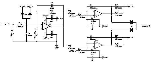
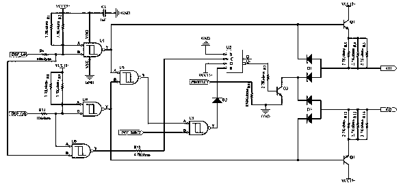
[0220] Such as figure 1 As shown, a wave-by-wave current limiting device for an inverter includes a voltage sampling module, a current sampling module, a micro-processing chip, a current comparison circuit, a wave-by-wave current limiting circuit and a power amplifier circuit, wherein,

[0221] The microprocessor chip is an enhanced STM32 series chip;

[0222] The current comparison circuit ...


PUM


Abstract

The invention discloses a wave-by-wave current limiting device for a inverter. When the inverter load is increased, the output power of the whole inverter increases, which inevitably leads to an increase in the load current. In order to avoid over-current of the main power circuit component switch tube, it is necessary to set a current threshold value in each switching cycle, so that the switch tube can be turned off when the switch tube current exceeds the threshold value, the current does not continue to rise to protect the switch tube. The wave-by-wave current limiting device for inverter can collect the load output current through a current limiting comparison unit and compare with the set value, and then perform a certain adjustment on the PWM waveform outputted by a chip through a wave-by-wave current limiting unit, and then output the signal to a power tube driving unit, thereby realizing current limiting during each switching cycle. Meanwhile, when the PWM waveform outputted bythe chip is wrong, the interlocking function can also be realized to prevent the DC power supply from being short-circuited due to the simultaneous conduction of the two switch tubes of the same bridge arm.

Description

technical field [0001] The present invention relates to the field of inverters, and more particularly, to a wave-by-wave current limiting device for inverters. Background technique [0002] PWM (Pulse Width Modulation, Pulse Width Modulation) control technology, with its simplicity, flexibility and good dynamic response, makes it the most common control method in the field of power electronics technology. [0003] The common current limiting method is to use PWM to control the current through current detection. This method does not limit the current in real time within one switching cycle. The chip cannot judge the current in time and adjust the PWM waveform. The switch tube is here There is still a risk of overcurrent during the time period. Contents of the invention [0004] The invention overcomes the defects of the existing current limiting method and provides a new wave-by-wave current limiting device for the inverter. When the current of the switch tube is higher t...

Claims


Application Information

Patent Timeline
Patent Type & Authority Applications(China)
IPC IPC(8): H02M1/32H02M1/08
CPCH02M1/32H02M1/08
Inventor 张志凌文胜
Owner DONGGUAN UNIV OF TECH
Why Eureka
Try Eureka