High-safety surge protection circuit and surge protection device

A surge protection and safety technology, applied in the field of power supply, can solve problems such as failure of protection circuit, failure of protection circuit of thermistor sheet 12, failure of varistor, etc.

Inactive Publication Date: 2018-11-23
CHENGDU TIEDA ELECTRONICS CORP
View PDF6 Cites 0 Cited by
  • Summary
  • Abstract
  • Description
  • Claims
  • Application Information

AI Technical Summary

Problems solved by technology

[0007] But this scheme still has some serious defects, at first because of the current-limiting effect of the positive temperature coefficient ceramic thermistor sheet 12, no matter how badly the piezoresistor sheet 11 deteriorates, the heating temperature is only maintained at the center of the thermistor sheet 12. Near the middle point temperature, it will not be disconnected from the grid and quit working until the varistor voltage value of the varistor sheet 12 deteriorates to about 1 / 2 of the peak value of the grid operating voltage. After the connection, the too low varistor voltage value clamps the grid current that is constantly following, so that the gas discharge tube 13 cannot return to the disconnected state, and the thermistor sheet 12 will be short-circuited, and the protection circuit will fail. At this time, the varistor sheet 11 will Immediate breakdown short circuit, causing serious short circuit fault
Theoretically, most varistors will fail in this way if there are no other protective measures
The other failure process is similar to the situation of scheme 1, that is, when the varistor sheet 11 deteriorates to a certain extent, even if it has not entered the accelerated deterioration zone, but because its internal structure has been severely damaged, its ability to withstand surge shocks The ability has been greatly reduced. At this time, a surge can break it down or nearly break it down. At this time, the gas discharge tube 13 is also in the conduction state, and the piezoresistor sheet 11 that is broken down or near the breakdown is also lost. The ability to clamp off the following current of the grid leads to the failure of the protection circuit of the thermistor sheet 12, resulting in a serious short-circuit fault

Method used


Image

  • High-safety surge protection circuit and surge protection device
  • High-safety surge protection circuit and surge protection device
  • High-safety surge protection circuit and surge protection device

Examples


Embodiment 1

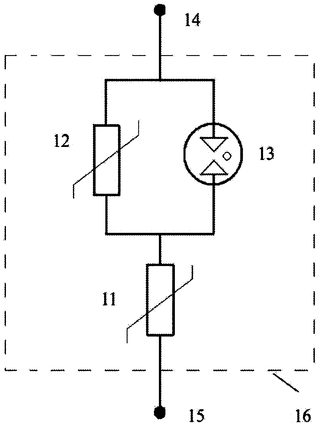
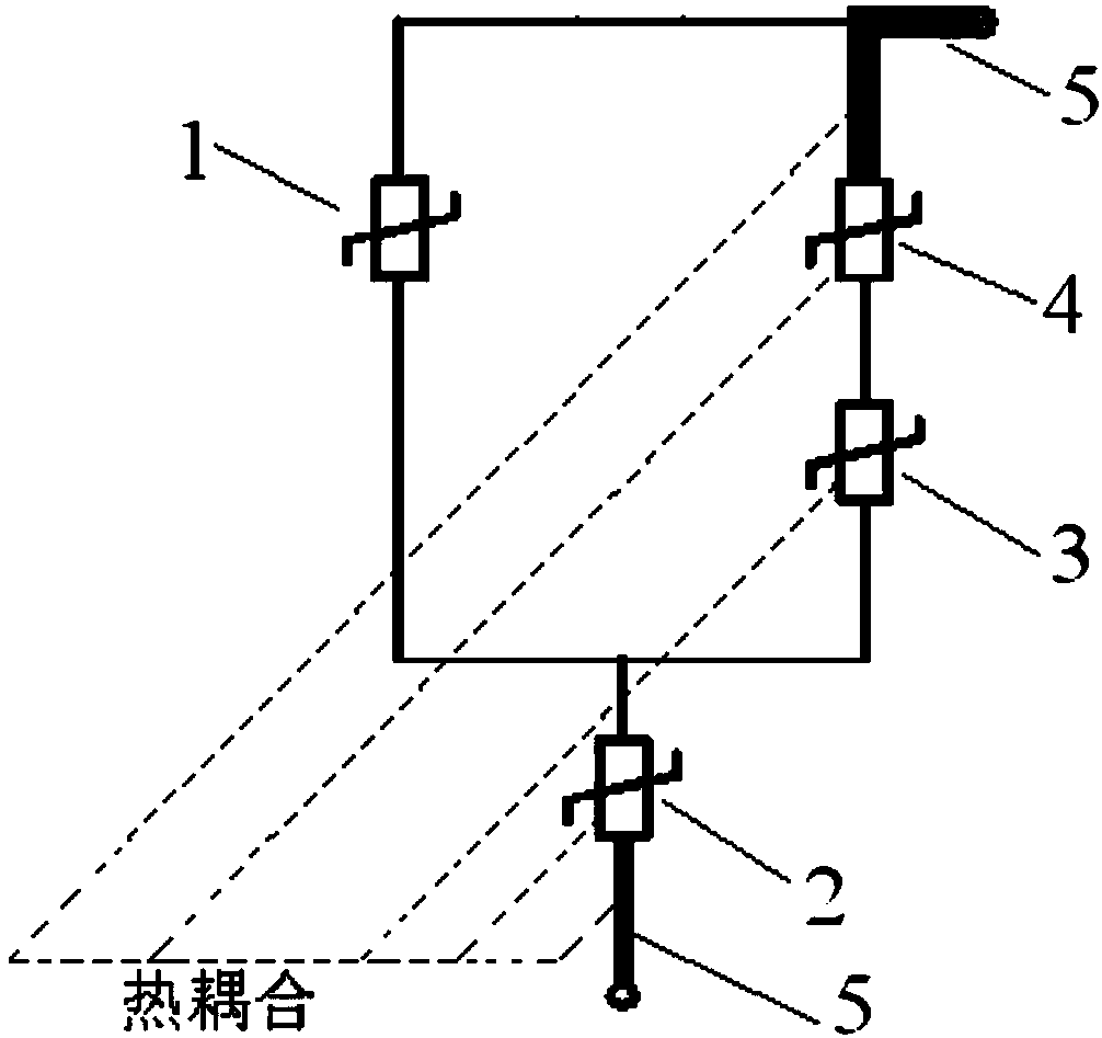
[0054] Such as image 3 As shown, a high-safety surge protection circuit includes a first varistor 1, a second varistor 2, a third varistor 3, a positive temperature coefficient thermistor 4 and a lead terminal 5 , the positive temperature coefficient thermistor sheet 4 is connected in parallel with the first varistor sheet 1 after being connected in series with the third varistor sheet 3, and the series-parallel branch is then connected with the second varistor sheet 2 in series to form a single-port combined circuit, wherein the performance of the first piezoresistor sheet 1 against surge impact is higher than that of the second piezoresistor sheet 2 .

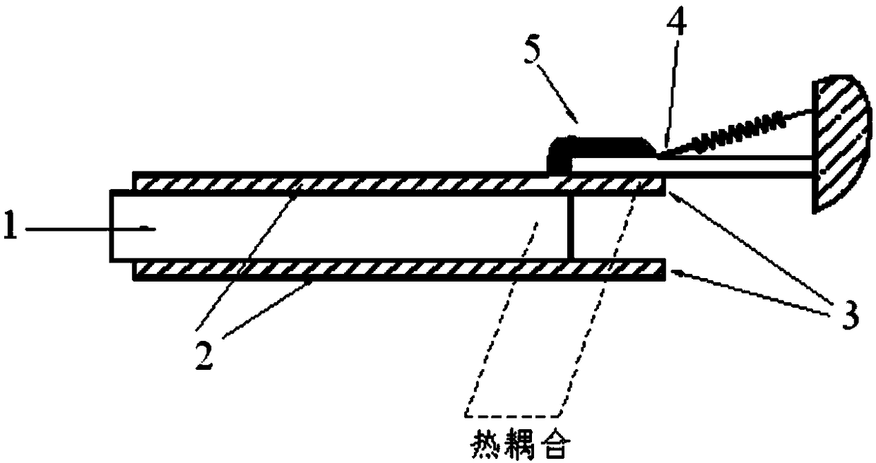
[0055] The two lead-out terminals 5 of the single-port combined circuit are both low thermal resistance heat-conducting terminals, the second varistor sheet 2 forms a thermal coupling with the third varistor sheet 3, and the third varistor sheet 3 forms a thermal coupling, and the third varistor sheet 3 forms a thermal coupl...

Embodiment 2

[0058] Such as Figure 4 As shown, the difference between this embodiment and Embodiment 1 is that only one of the two lead-out terminals 5 of the single-port combined circuit is a low thermal resistance heat conduction terminal, and the second varistor sheet 2 and the third varistor The sensitive resistor sheet 3 forms a thermal coupling, and the third piezoresistor sheet 3 forms a thermal coupling with the positive temperature coefficient thermistor sheet 4, and the low thermal resistance heat conduction terminal and the second piezoresistor sheet 2 thermally coupled to each other.

Embodiment 3

[0060] The difference between this embodiment and Embodiment 1 is that only one of the two lead-out terminals 5 of the single-port combined circuit is a low thermal resistance heat conduction terminal, and the second varistor sheet 2 and the third varistor sheet 3 to form a thermal coupling, and the third varistor sheet 3 and the positive temperature coefficient thermistor sheet 4 form a thermal coupling. The low thermal resistance heat conduction terminal is thermally coupled with the positive temperature coefficient thermistor sheet 4 (such as Figure 5 shown), or the thermal coupling between the low thermal resistance heat conduction terminal and the third piezoresistor sheet 3 (such as Figure 6 shown).


PUM


Abstract

The invention discloses a high-safety surge protection circuit and a surge protection device. The protection circuit comprises a first voltage-sensitive resistor piece, a second voltage-sensitive resistor piece, a third voltage-sensitive resistor piece, a positive temperature coefficient thermistor piece and a leading-out terminal, wherein the positive temperature coefficient thermistor piece andthe third voltage-sensitive resistor piece are connected in series and then connected with the first voltage-sensitive resistor piece in parallel, the series-parallel branch circuit and the second voltage-sensitive resistor piece are connected in series to form a single-port combination circuit. The surge impact withstanding performance of the first voltage-sensitive resistor piece is higher thanthat of the second voltage-sensitive resistor piece. At least one of the two leading-out terminals of the single-port combination circuit is a low-heat-resistance heat conduction end. The second voltage-sensitive resistor piece and the third voltage-sensitive resistor piece form thermal coupling, and the third voltage-sensitive resistor piece and the positive temperature coefficient thermistor sheet form thermal coupling, and the low-heat-resistance heat conduction end and one or two of the second voltage-sensitive resistor piece and the positive temperature coefficient thermistor piece are thermally coupled with each other at the same time.

Description

technical field [0001] The invention relates to the field of power supplies, in particular to a high-safety surge protection circuit and a surge protection device. Background technique [0002] Surge protector (SPD for short), as a standard low-voltage electrical appliance, is widely used in low-voltage transmission and distribution lines. Quality and ensuring the safety of electrical appliances have obvious effects. [0003] The core component of the SPD is a surge suppression component, the most commonly used is a varistor ceramic chip. Due to the long transmission distance of power transmission and distribution lines and their exposure to the open air, they are more likely to suffer from high-energy surge pulses than indoor electrical equipment. During the design life of the SPD, the varistor ceramic chips are more likely to be damaged beyond the rated specifications The multiple impacts of the high-energy surge caused the deterioration and failure of the varistor. Sin...

Claims


Application Information

Patent Timeline
Patent Type & Authority Applications(China)
IPC IPC(8): H02H9/04H02H7/00H02H3/20
CPCH02H3/20H02H7/008H02H9/042H02H9/044
Inventor 张治成叶磊詹俊鹄章俊石小龙
Owner CHENGDU TIEDA ELECTRONICS CORP
Why Eureka
Try Eureka