Rapid thermal annealing process capability monitoring method

A thermal annealing and process technology, applied in electrical components, semiconductor/solid-state device manufacturing, circuits, etc., can solve problems such as inability to effectively compensate for batch and batch variation fluctuations, reducing process windows, and different responses

Active Publication Date: 2018-11-23
SHANGHAI HUALI MICROELECTRONICS CORP
View PDF11 Cites 1 Cited by
  • Summary
  • Abstract
  • Description
  • Claims
  • Application Information

AI Technical Summary

Problems solved by technology

In the RTA process, the temperature setting for each area of ​​the wafer is a fixed value, but when the RTA process is performed, due to the process dispersion, the following two effects will be caused: the influence of the previous process leads to the temperature difference of the wafer in different areas of the RTA The different responses lead to the distribution of CMO device parameters in different regions of the wafer, which leads to a large spread of wafer electrical parameters and reduces the process window; due to the characteristics of the wafer manufacturing process, the process window at the edge of the wafer is narrow , and when the RTA process sets a uniform temperature in the wafer edge area, it cannot effectively compensate for the differences between batches and the fluctuations caused by the RTA process itself

Method used


Image

  • Rapid thermal annealing process capability monitoring method
  • Rapid thermal annealing process capability monitoring method
  • Rapid thermal annealing process capability monitoring method

Examples


Embodiment Construction

[0033] The specific implementation manner of the present invention will be described in more detail below with reference to schematic diagrams. The advantages and features of the present invention will be more apparent from the following description. It should be noted that all the drawings are in a very simplified form and use imprecise scales, and are only used to facilitate and clearly assist the purpose of illustrating the embodiments of the present invention.

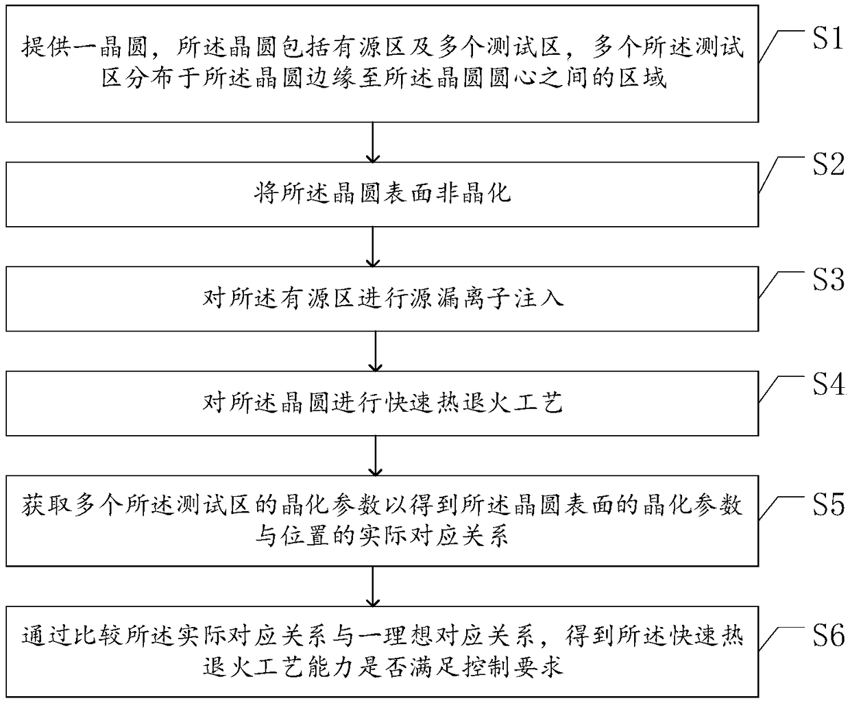
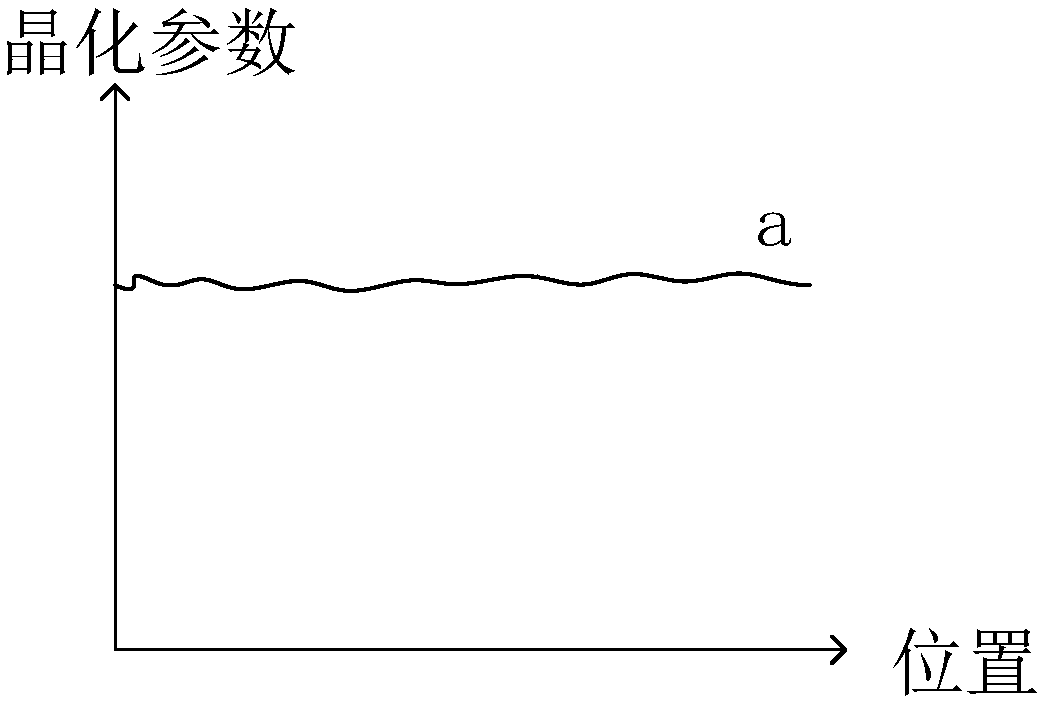
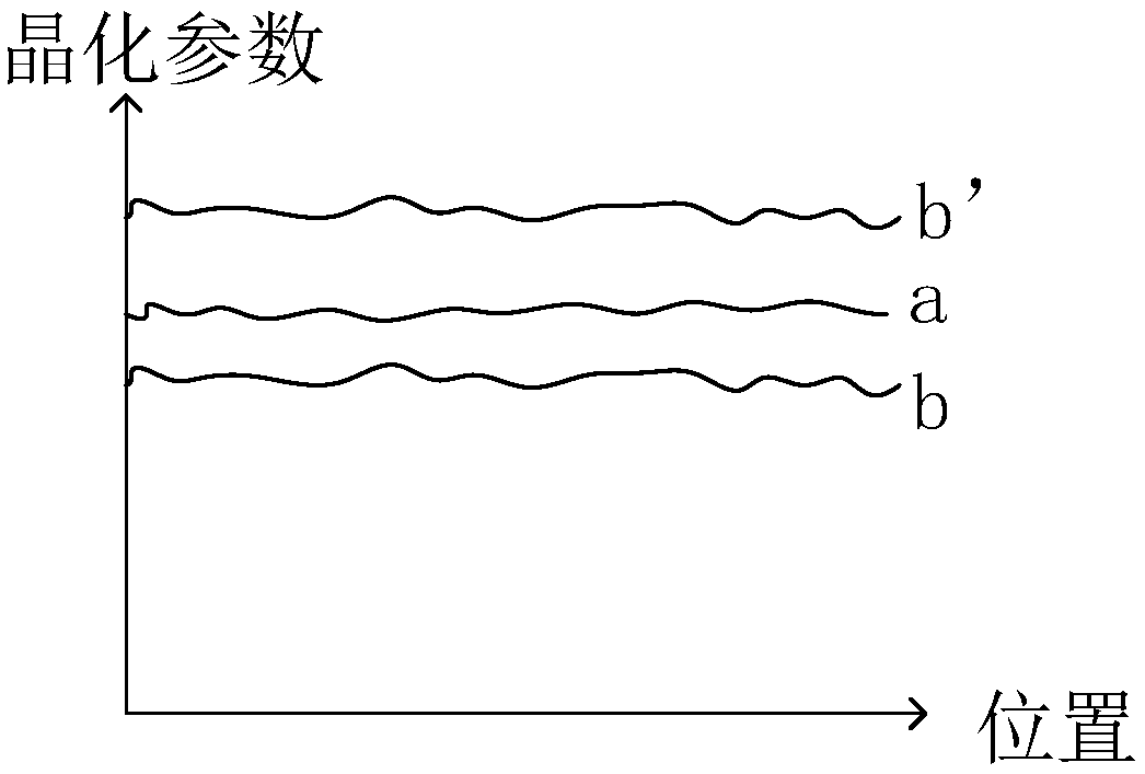
[0034] refer to figure 1 , which is a flow chart of the monitoring method for the rapid thermal annealing process capability provided in this embodiment, and the monitoring method for the rapid thermal annealing process capability includes:

[0035] S1: Provide a wafer, the wafer includes an active area and a plurality of test areas, and the plurality of test areas are distributed in the area between the edge of the wafer and the center of the wafer,

[0036] S2: amorphizing the surface of the wafer;

[0037] S3...


PUM

PropertyMeasurementUnit
sizeaaaaaaaaaa

Abstract

The invention provides a rapid thermal annealing process capability monitoring method. A plurality of test zones are arranged in an area between a wafer edge and a wafer circle center, and then the surface of the wafer is subjected to non-crystallizing; next, an active region is subjected to normal source-drain ion implantation and rapid thermal annealing process, wherein the rapid thermal annealing process is used for repairing and activating the impurities injected in the active region, and the crystal lattice defect caused by non-crystallizing of the surface of the wafer is repaired; the actual corresponding relation between the crystallization parameter of the surface and the position of the wafer is obtained by acquiring the crystallization parameters of the test region; the actual corresponding relation is compared with an ideal corresponding relation, and whether the rapid thermal annealing process capability meets the control requirements or not can be judged, so that the online monitoring of the rapid thermal annealing process is realized, and the performance difference of the device caused by differences between different batches of wafers is avoided.

Description

technical field [0001] The invention relates to the technical field of semiconductor manufacturing, in particular to a monitoring method for rapid thermal annealing process capability. Background technique [0002] The rapid thermal annealing process (Rapid Thermal Annealing, RTA) has an important application in the modern semiconductor industry. It can heat up extremely quickly and last for a short time at the target temperature to thermally anneal the silicon wafer. The rapid heating process and short duration An optimization can be achieved among repairing lattice defects, activating impurities, and minimizing impurity diffusion. [0003] CMOS devices are the main constituent units of integrated circuits. According to their manufacturing process and process, the RTA process has a strong correlation with the distribution of their electrical parameters in the wafer. Therefore, in order to improve the uniformity of chip CMOS devices in different regions of the wafer, Increa...

Claims


Application Information

Patent Timeline
Patent Type & Authority Applications(China)
IPC IPC(8): H01L21/265H01L21/324H01L21/67
CPCH01L21/265H01L21/324H01L21/67253
Inventor 崔冶青黄然邓建宁
Owner SHANGHAI HUALI MICROELECTRONICS CORP
Why Eureka
Try Eureka