Novel and convenient machine tool cone hole precision restoration instrument
A portable and machine tool technology, which is applied to the parts of grinding machine tools, machine tools designed for grinding the rotating surface of workpieces, grinding machines, etc., can solve the problems of unstable speed, low rotation accuracy, and low work efficiency, and achieve easy installation With the effect of disassembly, high rotation precision and large fixed area
- Summary
- Abstract
- Description
- Claims
- Application Information
AI Technical Summary
Problems solved by technology
Method used
Image
Examples
Embodiment 1
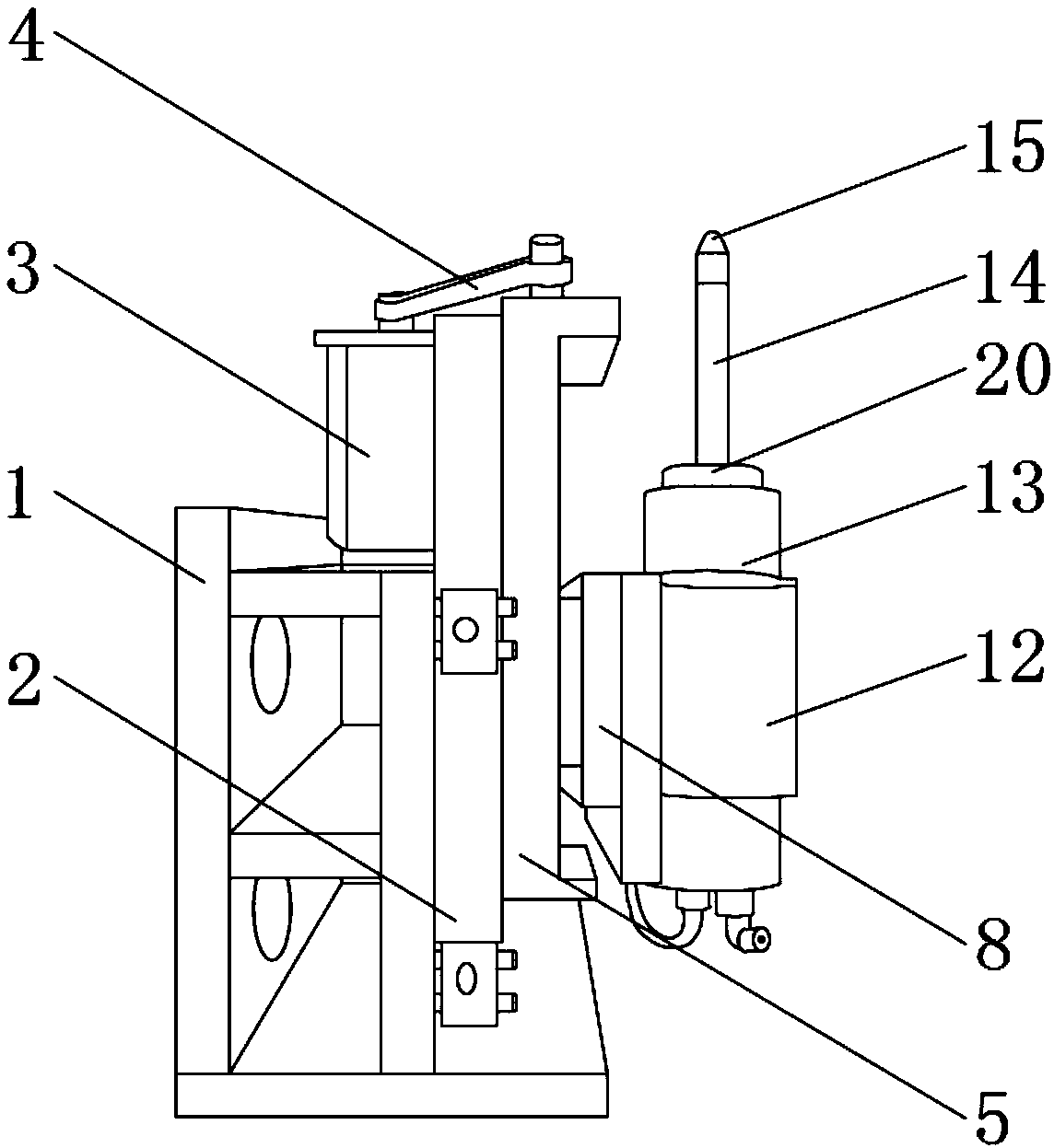
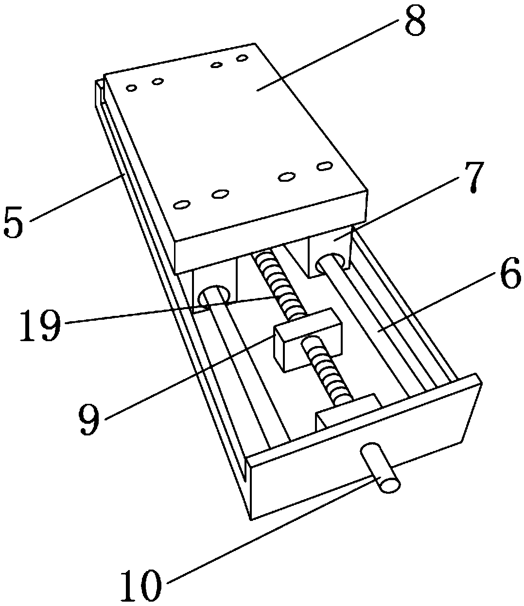
[0026] Such as Figure 1-5 As shown, a new type of portable machine tool taper hole precision repairing instrument includes a base 1 and a rotary table 2, the base 1 is located on one side of the rotary table 2, and a motor 3 is fixedly installed on the upper side of the rotary table 2 , and the motor 3 is located at the upper end of the base 1, the upper end of the motor 3 is provided with a main shaft, and the outer surface of the main shaft is provided with a belt 4, and the other side of the rotary table 2 is fixedly installed with a guide rail plate 5, and the inside of the guide rail plate 5 Two sets of single guide rails 6 are fixedly installed, and the outer surfaces of the two sets of single guide rails 6 are provided with single guide rail sliders 7, one side of the two sets of single guide rail sliders 7 is fixedly installed with a sliding workbench 8, and the inner middle of the guide rail plate 5 A fixed block 9 is installed in a fixed position, and the fixed bloc...
Embodiment 2
[0028] Such as Figure 1-5 As shown, a new type of portable machine tool taper hole precision repairing instrument, the other side of the sliding table 8 is fixedly installed with a screw hole block, and the screw 19 runs through the inside of the screw hole block, and the screw hole 19 is threaded with the screw hole block Connection, No. 1 positioning rotating shaft 17 and No. 2 moving rotating shaft 18 are both movably connected with the adjustment block 16, and the adjustment block 16 is movably connected with the rotary table 2, and the two groups of single guide rails 6 are respectively movable with the two groups of single guide rail sliders 7 connection, the inner center of the fixed block 9 is provided with a threaded hole, and the fixed block 9 is threaded with the lead screw 19, and one end of the motor 3 and the grinding head motor 13 is fixedly installed with several groups of wires, and the conductive side is fixedly installed with Control panel, one side of the ...
Embodiment 3
[0030] Such as Figure 1-5 As shown, a new type of portable machine tool taper hole precision repairing instrument, the rotary bearing is fixedly installed in the inner center of the rotary table 2, the rotary bearing is fixedly connected with the base 1, and the rotary table 2 and the base 1 move through the rotary bearing connection, the synchronous pulley 10 is flexibly connected to the main shaft through the belt 4, and the synchronous pulley 10 runs through one side of the guide rail plate 5, the rotating speed of the electric main shaft 20 is 40000 rpm, and the vibration value of the electric main shaft 20 is 0.1mm / s, and the dynamic balance grade of the electric spindle 20 is G0.4, the fixed area of the rotary table 2 and the base 1 is large, which can provide stable support during work and effectively reduce vibration, and the grinding rod 14 and the grinding head motor 13 are integrated The grinding wheel 15 butts with the tapered hole to repair the precision, the ...
PUM
 Abstract
Description
Claims
Application Information
 - R&D Engineer
- R&D Manager
- IP Professional
- Industry Leading Data Capabilities
- Powerful AI technology
- Patent DNA Extraction
Browse by: Latest US Patents, China's latest patents, Technical Efficacy Thesaurus, Application Domain, Technology Topic, Popular Technical Reports.
© 2024 PatSnap. All rights reserved.Legal|Privacy policy|Modern Slavery Act Transparency Statement|Sitemap|About US| Contact US: help@patsnap.com


