
Control method and system for improving quality of output waveform of grid-connected converter

An output waveform and control method technology, applied in the control field of improving the output waveform quality of grid-connected converters, can solve the problems of complex controller structure, reduced system response speed, lack of sufficient suppression of harmonics, etc.

Active Publication Date: 2018-11-16
唐瑭
View PDF6 Cites 4 Cited by
  • Summary
  • Abstract
  • Description
  • Claims
  • Application Information

AI Technical Summary

Problems solved by technology

[0002] With the development of power electronics technology and the extensive use of high-performance chips, the requirements for the response speed and control accuracy of the control system to the command value signal are gradually improved, and the proportional-integral (PI) controller can realize the non-static tracking of the DC input signal , but lacks sufficient suppression of harmonics
Proportional-derivative (PR) controllers can effectively suppress harmonics of a specific frequency. When the system needs to suppress harmonics of different frequencies, a large number of PR controllers are required to be connected in parallel, resulting in a complex controller structure.
[0003] The control block diagram of proportional integral + repetitive control is as follows figure 2 As shown, the repetitive controller will accumulate the error value at the current moment and the error value at the same moment of the previous fundamental wave cycle as the output signal at the same moment of the next fundamental wave cycle, so when the command signal changes step by step, the repetitive control Unable to respond immediately, resulting in slow system response
After the proportional-integral controller is connected in parallel, the proportional-integral controller can immediately respond to the step signal of the command signal, quickly track the change of the command signal, and improve the system response speed. However, during the dynamic response process, the actual value of the controlled variable is different from the The error value between the command values ​​will be stored in the repeating controller and output at the same moment of the next fundamental wave cycle, this error will cause the output current of the grid-connected inverter to be distorted
[0004] In summary, there is currently a lack of a method for controlling the above-mentioned error signal

Method used


Image

  • Control method and system for improving quality of output waveform of grid-connected converter
  • Control method and system for improving quality of output waveform of grid-connected converter
  • Control method and system for improving quality of output waveform of grid-connected converter

Examples


Embodiment 1

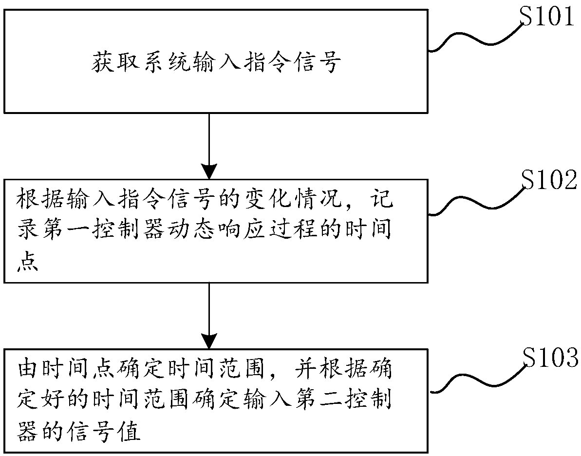
[0049] refer to figure 1 , the control methods to improve the output waveform quality of the grid-connected converter include:

[0050] Step S101, acquiring a system input instruction signal;

[0051] Step S102, recording the time point of the dynamic response process of the first controller according to the change of the input instruction signal;

[0052] Step S103, determine the time range from the time point, and determine the signal value input to the second controller according to the determined time range.

[0053] Specifically, the embodiment of the present invention provides a control strategy for controlling the output waveform quality of the grid-connected converter by adopting proportional integral + repetition, so as to solve the problem of the output waveform quality of the converter. The principle of the method is: in any fundamental wave period, when the system input command signal has a step, record the start time point and end time of the dynamic response p...

Embodiment 2

[0080] figure 2 It is a block diagram of proportional integral + repetitive control structure,

[0081] figure 2 Among them, r(z) is the command value of the input signal, e(z) is the difference, and G pi (z) is the proportional-integral controller transfer function, z -N is a delay link of a fundamental period, Q(z)z -N In Q(z) is usually set to a constant of 0.95, S(z) is a stabilizer compensator, G p (z) is the control object. It can be seen from the figure that when r(z) has a step response, G pi (z) The error disturbance signal generated during the dynamic response process will be directly superimposed into the repetitive controller through the feedback loop, which will lead to the distortion of the output waveform of the grid-connected inverter.

[0082] image 3 It is a block diagram of a control strategy for improving the output waveform quality of a grid-connected converter using proportional integral + repetitive control proposed by the embodiment of the prese...

Embodiment 3

[0086] refer to Figure 4 , the control system to improve the output waveform quality of the grid-connected converter includes:

[0087] An acquisition unit 10, configured to acquire a system input command signal;

[0088] The recording unit 20 is configured to record the time point of the dynamic response process of the first controller according to the change of the input instruction signal;

[0089] The determination unit 30 is configured to determine the time range from the time point, and determine the signal value input to the second controller according to the determined time range.


PUM


Abstract

The invention provides a control method and system for improving the quality of an output waveform of a grid-connected converter, and the method comprises the steps: obtaining an input instruction signal of a system; recording a time point of a dynamic response process of a first controller according to the change conditions of the input instruction signal; determining a time range through the time point, and determining a signal value inputted into a second controller according to the determined time range. The method achieves the screening of the inputted repeated control signals, prevents an error signal of a PI (Proportional-Integral) controller in a dynamic response process from being inputted into a repetition controller, guarantees that a value inputted into the repetition controller is always composed of a real value in a conventional or current period, and guarantees the quality of an output signal of the controller.

Description

technical field [0001] The invention relates to the technical field of power electronics and automatic control, in particular to a control method and system for improving the output waveform quality of a grid-connected converter. Background technique [0002] With the development of power electronics technology and the extensive use of high-performance chips, the requirements for the response speed and control accuracy of the control system to the command value signal are gradually improved, and the proportional-integral (PI) controller can realize the non-static tracking of the DC input signal , but lacks sufficient suppression of harmonics. Proportional-derivative (PR) controllers can effectively suppress harmonics of a specific frequency. When the system needs to suppress harmonics of different frequencies, a large number of PR controllers need to be connected in parallel, resulting in a complex controller structure. [0003] The control block diagram of proportional int...

Claims


Application Information

Patent Timeline
Patent Type & Authority Applications(China)
IPC IPC(8): G05B11/42
CPCG05B11/42
Inventor 唐瑭
Owner 唐瑭
Learn More