
Catalytic combustion waste gas treatment system for medium and small air volumes

A technology for waste gas treatment and catalytic combustion, applied in the combustion method, combustion type, incinerator, etc., can solve the problems of too fast empty bed flow rate of waste gas, uneven distribution of heating pipes, no supplementary cooling system, etc., to optimize catalytic combustion process, reduced heat loss, small footprint effect

Pending Publication Date: 2018-11-16
江苏诺伊拓环保工程有限公司
View PDF1 Cites 7 Cited by
  • Summary
  • Abstract
  • Description
  • Claims
  • Application Information

AI Technical Summary

Problems solved by technology

The adsorption method mainly uses the adsorption material to absorb and concentrate the pollutants in the exhaust gas to purify the exhaust gas. However, once the adsorption material (such as activated carbon, molecular sieve, etc.) is saturated, it needs to be replaced or regenerated, and has a certain service life. The problem of hazardous waste has always been the main reason limiting the wide application of adsorption technology.
The device has defects such as complex structure, uneven distribution of heating tubes, excessive flow velocity of exhaust gas empty bed, and inconspicuous catalytic effect.
And the device is not equipped with a supplementary cooling system. When the concentration of exhaust gas is high, once the equipment cannot withstand the instantaneous thermal shock, it will cause safety hazards or even explode.

Method used


Image

  • Catalytic combustion waste gas treatment system for medium and small air volumes
  • Catalytic combustion waste gas treatment system for medium and small air volumes

Examples


Embodiment Construction

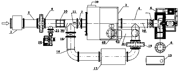
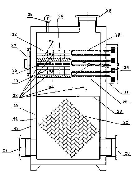
[0029] In order to enable those skilled in the art to better understand the technical solutions of the present invention, the following Figure 1-2 The technical solutions of the present invention are further described with the examples.

[0030] It should be noted that the embodiments provided by the present invention are only for the purpose of effectively explaining the technical features of the present invention, and the positioning words such as the left side, the right side, the upper end, the lower end, etc. are only for the purpose of improving the embodiments of the present invention. The description should not be regarded as a limitation on the technical solution of the present invention.

[0031] The present invention is aimed at industrial air volume at 500m 3 / h~20000m 3 / h of the organic waste gas treatment industry, especially the waste treatment system that cannot contain chlorine, phosphorus, arsenic, sulfur, and mercury, tin, zinc and other substances that ...


PUM


Abstract

The invention discloses a catalytic combustion waste gas treatment system for medium and small air volumes. The catalytic combustion waste gas treatment system for the medium and small air volumes issequentially provided with a dry type filtering device, an intake pipeline, a heat exchange type catalysis and oxidation integrated machine, an exhaust pipeline, an induced draft fan and a chimney. Anintake valve is arranged at the intake end of the heat exchange type catalysis and oxidation integrated machine. A safety control system is arranged between the intake valve and the dry type filtering device. The safety control system communicates with a coldness supplementation system and a bypass system. An emergency discharge system is arranged on the heat exchange type catalysis and oxidationintegrated machine. A PLC control cabinet is electrically connected with the whole waste gas treatment system. The catalytic combustion waste gas treatment system for medium and small air volumes islow in power and small in energy consumption and meets various complicated working conditions; through the additional arrangement of the safety control system and a coldness supplementation diluting system, full-process monitoring and data storage are conducted on temperature and pressure in the combustion process, and self-adjustment of heating power is conducted according to the combustion statein the combustion process; and in this way, the system operation safety and stability are greatly improved.

Description

technical field [0001] The invention relates to the field of exhaust gas treatment equipment, in particular to a catalytic combustion exhaust gas treatment system for medium and small air volumes. Background technique [0002] At present, the treatment methods of industrial VOCs waste gas treatment industry for waste gas pollution components are mainly divided into: destruction and recycling. For the working conditions where there is no recovery value in the exhaust gas and the concentration of the exhaust gas is relatively high, the combustion method is mostly used for treatment. The combustion method is mainly divided into: incineration and catalytic combustion. Catalytic combustion is a typical gas-solid phase catalytic reaction. It reduces the activation energy of the reaction with the help of a catalyst, enabling it to carry out flameless combustion at a lower light-off temperature of 250°C to 430°C. The oxidation of organic substances occurs on the surface of the solid...

Claims


Application Information

Patent Timeline
Patent Type & Authority Applications(China)
IPC IPC(8): F23G7/07F23G7/06F23G5/50F23G5/46
CPCF23G5/46F23G5/50F23G7/063F23G7/07F23G2202/102F23G2206/10F23G2208/10F23G2207/30
Inventor 李洋
Owner 江苏诺伊拓环保工程有限公司
Learn More