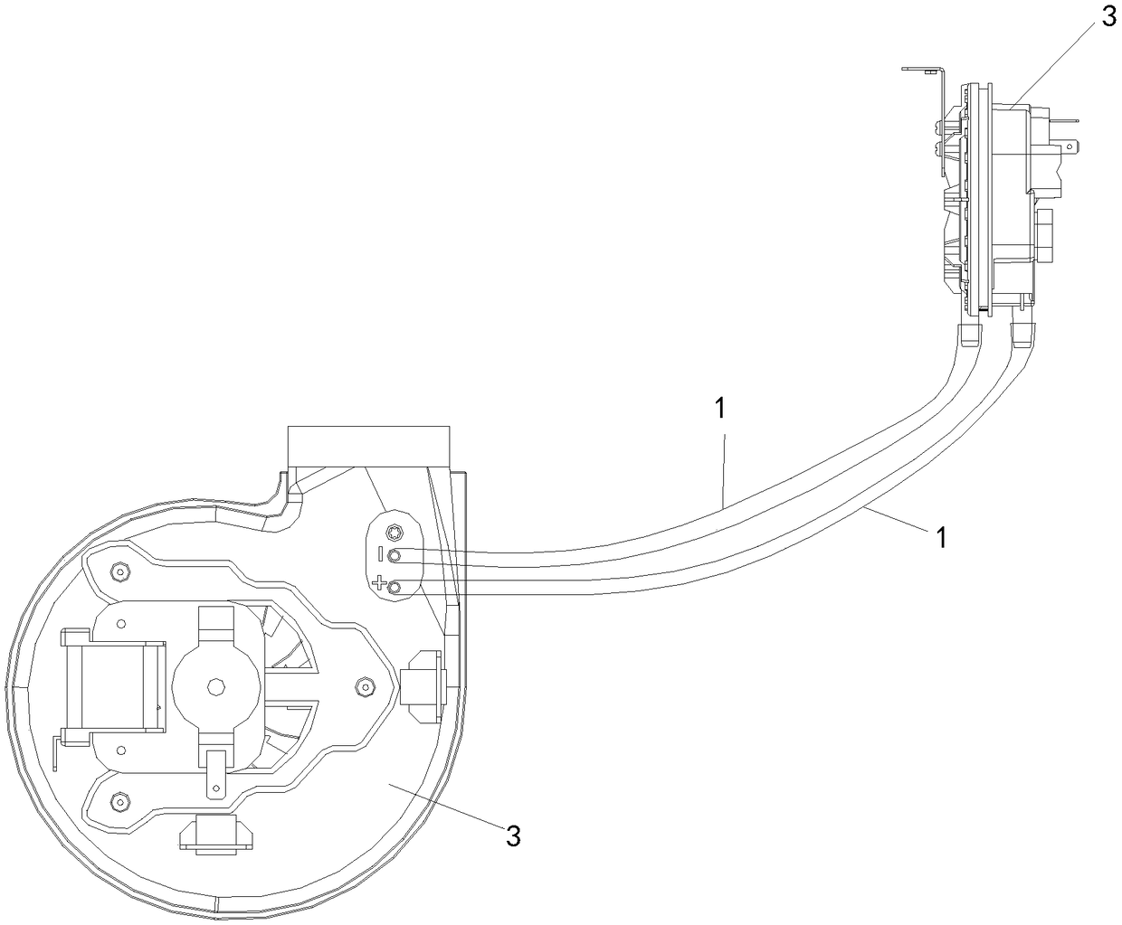
Wind pressure pipe, wall-mounted furnace and method of reducing using failure of wall-mounted furnace
A technology of air pressure and pipes, which is applied in the field of wall-hung boilers and reducing the failure of wall-hung boilers, and the field of air pressure pipes. It can solve the problems of high maintenance costs and high failure rates, reduce replacement costs, increase service life, and reduce air pressure switches. short circuit effect
- Summary
- Abstract
- Description
- Claims
- Application Information
AI Technical Summary
Problems solved by technology
Method used
Image
Examples
Embodiment 1
[0044] Such as Figure 1-Figure 7 Shown:
[0045] A wind pressure pipe provided by the present invention includes a pipe body 1 and a condensed water discharge device 4 arranged on the pipe body 1. The pipe body 1 is provided with a condensed water outlet and an air outlet, and the air outlet is used for When connected to the air pressure switch 2 , the condensed water discharge device 4 can discharge the condensed water condensed and precipitated by the airflow in the pipe body 1 from the condensed water outlet to the outside of the pipe body 1 .
[0046] In the air pressure pipe provided by the embodiment of the present invention, the condensed water discharge device 4 can discharge the condensed water that is condensed and precipitated by the airflow in the pipe body 1 from the condensed water outlet to the outside of the pipe body 1; The air pressure switch 2 is short-circuited due to the condensed water blocking the air pressure pipe or the condensed water entering the a...
Embodiment 2
[0059] Such as Figure 8 Shown:
[0060] The difference between Embodiment 2 and Embodiment 1 is that the condensed water discharge device 4 is a corrosion-resistant heat conduction member 401 inserted at the condensed water outlet of the pipe body 1, and the heat conduction member 401 is inserted obliquely, and At least the lower end of the heat conducting element 401 is inserted at the condensed water outlet of the pipe body 1 and protrudes outside the pipe body 1 (preferably both ends of the heat conducting element 401 protrude outside the pipe body 1).
[0061] As an optional implementation manner, the heat conduction member 401 is a heat conduction wire (preferably a heat conduction wire with a diameter of 0.5mm-1.5mm) or a heat conduction sheet.
[0062] As an optional embodiment, the heat conducting member 401 is made of Q215, Q235 (preferably Q235), Q255, No. 08 steel, No. 10 steel, No. 15 steel, No. 20 steel, No. 40 steel or No. 45 steel.
[0063] In this embodiment...
Embodiment 3
[0068] Such as Figure 9 with Figure 10 Shown:
[0069] The difference between this embodiment 3 and embodiment 1 is that the condensed water discharge device 4 is a drain pipe obliquely connected to the condensed water outlet, one end of the drain pipe extends into the pipe body 1, and the other end of the drain pipe The one-way valve 7 is connected, and the end connected with the one-way valve 7 is lower than the end extending into the pipe body 1; when installing the wall-hung boiler, the end of the drain pipe connected with the one-way valve 7 protrudes out of the sealed chamber 5 outside.
[0070] As an optional embodiment, the end surface of the end of the drainage pipe protruding into the pipe body 1 is inclined, the top of this end is flush with the inner wall of the pipe body 1 , and the bottom of this end extends into the pipe body 1 .
[0071] As an optional embodiment, the internal diameter of the drain pipe is 2.0mm-3.0mm (preferably 2.5mm); since the cross-se...
PUM
 Abstract
Description
Claims
Application Information
 - R&D
- Intellectual Property
- Life Sciences
- Materials
- Tech Scout
- Unparalleled Data Quality
- Higher Quality Content
- 60% Fewer Hallucinations
Browse by: Latest US Patents, China's latest patents, Technical Efficacy Thesaurus, Application Domain, Technology Topic, Popular Technical Reports.
© 2025 PatSnap. All rights reserved.Legal|Privacy policy|Modern Slavery Act Transparency Statement|Sitemap|About US| Contact US: help@patsnap.com


