
Downwards-blowing air conditioner system for engineering machine

A technology for air-conditioning systems and construction machinery, which is applied in air-handling equipment, heating/cooling equipment, transportation, and packaging, etc. Frost can not be used normally, reduce performance, reduce the effect of failure rate

Inactive Publication Date: 2014-10-08
北京松芝汽车空调有限公司
View PDF6 Cites 0 Cited by
  • Summary
  • Abstract
  • Description
  • Claims
  • Application Information

AI Technical Summary

Problems solved by technology

However, the current air conditioners for construction machinery all have a fan suction structure, that is, although the fan is located above the air conditioner, the fan is of the suction type, and the wind entering the air conditioning box first passes through the evaporator core and the warm air core before reaching the fan. The air volume entering the fan is lost due to excessive wind resistance
Moreover, since the water produced by the evaporator core should be drained from the drip hole at the bottom of the air conditioner box, under the action of the suction force on the fan, it is not conducive to the drainage of the system, which increases the hidden danger of frosting in the air conditioner
At the same time, it increases the possibility that the fan will inhale the water generated by the evaporator. After the water enters the fan, there will be a potential short circuit of the fan, which will affect the performance of the air conditioner, that is, the comfort in the car.

Method used


Image

  • Downwards-blowing air conditioner system for engineering machine

Examples


Embodiment Construction

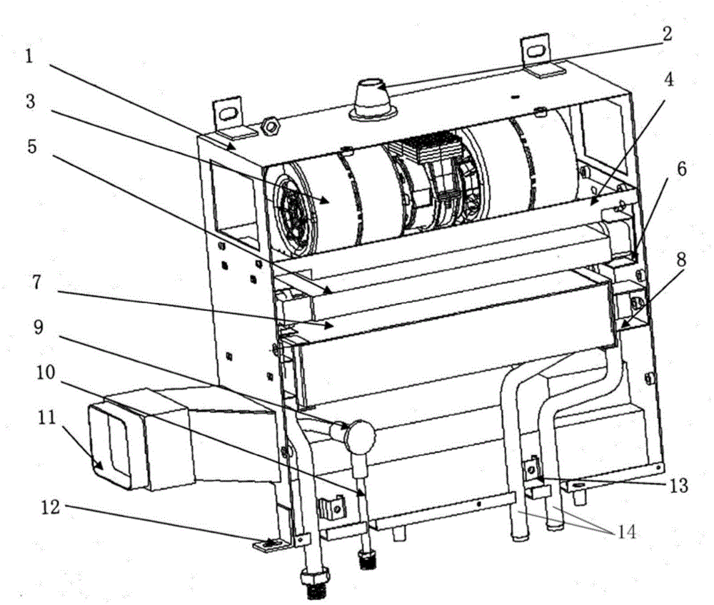
[0012] The object of the present invention is to provide a down-blown air conditioning system for construction machinery. The specific implementation of the present invention will be described in detail below with reference to the accompanying drawings.

[0013] figure 1 As shown, a rubber sleeve 2 is arranged on the top surface of the air-conditioning box 1, and the double-impeller centrifugal fan 3 is defined on the fan support 4 in the upper part of the air-conditioning box 1. Below the fan support 4, the warm air core support 6 is fixed on the air-conditioning box. On the inner wall of the body 1, and support the warm air core 5; the evaporator core 7 is fixed under the warm air core support 6 by the evaporator core support 8, and the pipe clamp support 13 connects the refrigerant pipeline 10 of the air conditioning system and the condensation The water pipe 14 is supported on the inner wall of the air conditioning box 1, the refrigerant pipeline 10 and the condensate wate...


PUM


Abstract

The invention discloses a downwards-blowing air conditioner system for an engineering machine and belongs to the field of air conditioners of automobiles. A double-impeller centrifugal fan, a warm air core and an evaporator core are arranged in an air conditioner box body from top to bottom. An expansion valve is installed in a refrigerant pipeline. The refrigerant pipeline and a condensate pipe are both connected with the evaporator core. A transmission air duct and multiple box body installation supports are arranged on the outer walls on the top surface and the side surface of the air conditioner box body. Air of the double-impeller centrifugal fan enters an air conditioner from the side surface of the box body and then is blown downwards, and air passes through the warm air core, so that coldness generated by the evaporator core is blown into a cab through the transition air duct. The generated coldness is blown into the cab under the drive of a draught fan, and therefore the refrigeration comfortable effect is achieved. According to the downwards-blowing air conditioner system for the engineering machine, due to the novel downwards-blowing structure, the thickness of the warm air core is reduced, the short-circuit faults caused by water accumulation of the draught fan is reduced greatly, the blast capacity of the air conditioner system is increased; space in the cab in the engineering machine is often wide, and therefore the requirement for the structure of the air conditioner and the appearance of the air conditioner is not high.

Description

technical field [0001] The invention belongs to the scope of automobile air conditioners, in particular to a down-blown air conditioner system for engineering machinery. Background technique [0002] The automotive air conditioning system is a device that cools, heats, ventilates and purifies the air in the cabin. It can provide a comfortable riding environment for the passengers, reduce the driver's fatigue intensity and improve driving safety. [0003] Due to the harsh working environment and unsatisfactory sealing of construction machinery, improving system performance and reducing failures are of great significance to ensure the normal operation and working comfort of the air conditioner of construction machinery. However, the current air conditioners for construction machinery all have a fan suction structure, that is, although the fan is located above the air conditioner, the fan is of the suction type, and the wind entering the air conditioning box first passes throu...

Claims


Application Information

Patent Timeline
Patent Type & Authority Applications(China)
IPC IPC(8): B60H1/00
Inventor 赵艳华孙凯民付亭徐昌昊
Owner 北京松芝汽车空调有限公司
Learn More