Eureka AIR delivers breakthrough ideas for toughest innovation challenges, trusted by R&D personnel around the world.
Five-bar linkage for aspheric component polishing
What is Al technical title?
Al technical title is built by PatSnap Al team. It summarizes the technical point description of the patent document.
An aspheric, five-link technology, used in grinding/polishing equipment, control of workpiece feed motion, grinding frame, etc. Response, inability to effectively suppress intermediate frequency errors, etc., to achieve the effects of simple and reliable mechanism control, shortened measurement time, and high reliability
Active Publication Date: 2020-09-15
SHANGHAI INST OF OPTICS & FINE MECHANICS CHINESE ACAD OF SCI
View PDF9 Cites 0 Cited by
Summary
Abstract
Description
Claims
Application Information
AI Technical Summary
This helps you quickly interpret patents by identifying the three key elements:
Problems solved by technology
Method used
Benefits of technology
Problems solved by technology
[0005] The mechanism actively controls the trajectory of the polishing disc through the motor. The mass of the mechanism is large, and the motor cannot respond at high speed and high precision according to the surface shape of the workpiece, resulting in inflexible movement of the polishing disc and high requirements for the trajectory synthesis of the control and execution system;
[0006] Because the mechanism synthesizes the trajectory through the motor, the polishing disc and the workpiece cannot be completely attached, and the resulting uneven and uncontrollable pressure will lead to uneven removal, resulting in large processing errors
[0007] In summary, the above-mentioned invention cannot guarantee higher processing quality, and is not enough to replace the manual polishing method
[0008] Traditional computer-controlled surface shaping (CCOS) technology plans a relatively orderly polishing path, has low processing flexibility, and cannot effectively suppress the intermediate frequency error caused by orderly processing. In many cases, skilled workers are still required to manually repair and polish. Repairing and polishing has the disadvantages of high labor intensity, the surface shape cannot be precisely controlled, and experienced operators are required.
Method used
Image
Click on the blue label to locate the original text in one second.
Reading with bidirectional positioning of images and text.
Examples
Embodiment Construction
[0045] The preferred embodiments of the present invention will be described in detail below in conjunction with the accompanying drawings.
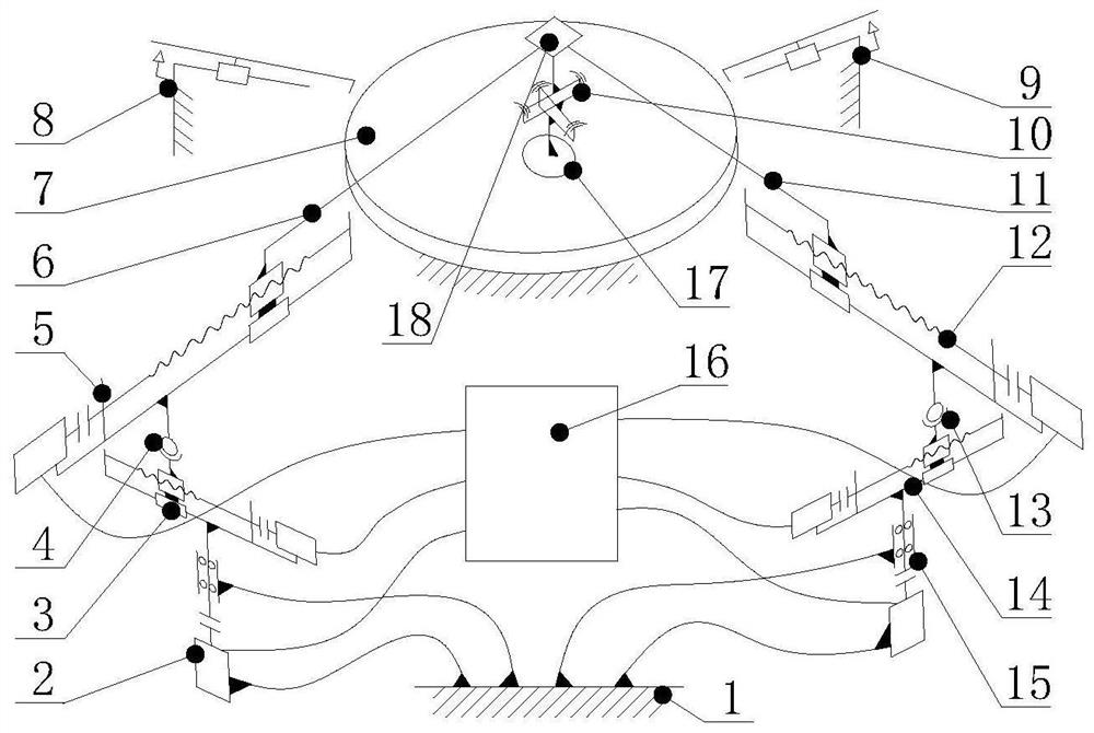
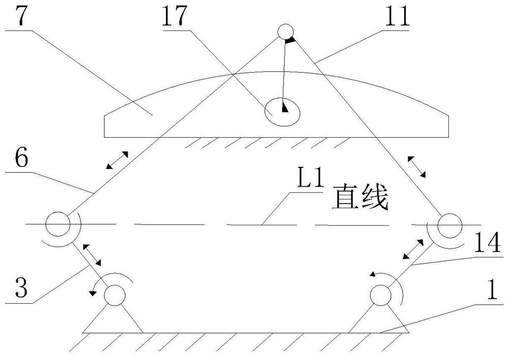
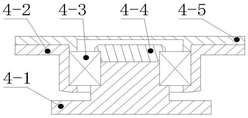
[0046] See figure 1 and figure 2 , figure 1 It is a schematic diagram of a five-bar linkage mechanism used for aspheric element polishing in the present invention, figure 2 It is a schematic diagram of the five-bar linkage mechanism used for polishing aspheric elements of the present invention. It can be seen from the figure that the five-bar linkage mechanism used for polishing aspheric elements in the present invention includes: a frame 1, a first spindle device 2, a first crank slide 3, a first spherical joint mechanism 4, and a first link slide 5. The first connecting rod 6, the workpiece 7, the first positioning measuring tool 8, the second positioning measuring tool 9, the floating head 10, the second connecting rod 11, the second connecting rod sliding table 12, the second ball joint mechanism 13, the second crank slide 14, s...
PUM
Abstract
The invention discloses a five-linkage-rod mechanism for non-spherical element polishing. The mechanism mainly comprises a machine frame, main shafts, crank sliding tables, spherical hinge mechanisms,connecting rod sliding tables, connecting rods, a workpiece, positioning measuring tools, a floating head, a control box, a pitch lap and a rapid disassembling module, the two main shafts, the cranksliding tables, the spherical hinge mechanisms, the connecting rod sliding tables and the connecting rods form the closed two-spherical-hinged three-degree-of-freedom five-rod mechanism, the two positioning measuring tools accurately determine the position of the workpiece relative to the two main shafts, the control box is used for controlling the rotating speed and the rotating angle of the mainshafts, the length of the crank sliding tables and the length of the connecting rod sliding tables through reading codes, and the connecting rods drive the pitch lap to realize polishing machining. The five-linkage-rod mechanism is a mechanism which is based on three-degree-of-freedom five-connecting-rod mechanism based on the two-spherical-hinged three-degree-of-freedom five linkage rods, controllable residence time type polishing is realized according to the traditional manual polishing characteristic design, the mechanism is suitable for various non-spherical elements, the single removal amount can be controlled at the nanometer level, and the advantages of being flexible in movement, high in reliability, high in machining quality, capable of effectively restraining medium-frequency errors and the like are achieved.
Description
technical field [0001] The invention relates to optical processing, in particular to a five-link mechanism for polishing aspherical elements, which is applicable to ultra-precise polishing of complex aspheric elements. [0002] technical background [0003] Aspheric elements are widely used in optical systems, which can improve aberration correction capabilities, improve image quality, expand field of view, increase operating distance, reduce system costs and effectively reduce equipment quality. One of the important parts. [0004] In the patent "Numerical Control Double Pendulum Mechanism for Polishing Aspheric Optical Elements" (Patent Publication No. CN106826543A), a numerical control double pendulum mechanism for aspheric optical elements is introduced. This mechanism performs polishing by automatically adjusting the height of the polishing disc. There are two main problems: [0005] The mechanism actively controls the trajectory of the polishing disc through the motor...
Claims
Application Information
Patent Timeline
Application Date:The date an application was filed.
Publication Date:The date a patent or application was officially published.
First Publication Date:The earliest publication date of a patent with the same application number.
Issue Date:Publication date of the patent grant document.
PCT Entry Date:The Entry date of PCT National Phase.
Estimated Expiry Date:The statutory expiry date of a patent right according to the Patent Law, and it is the longest term of protection that the patent right can achieve without the termination of the patent right due to other reasons(Term extension factor has been taken into account ).
Invalid Date:Actual expiry date is based on effective date or publication date of legal transaction data of invalid patent.