Synchronous source automatic selection circuit for power meter

An automatic selection and synchronization source technology, applied in the direction of measuring electrical variables, measuring devices, instruments, etc., can solve the problems of affecting the test speed of the instrument, timing delay, timing accuracy reduction, affecting the timeliness and accuracy of ADC sampling, etc., to achieve Improve measurement efficiency and accuracy, improve accuracy and real-time performance, and avoid unstable program operation

Pending Publication Date: 2018-11-09
CHANGZHOU TONGHUI ELECTRONICS
View PDF1 Cites 0 Cited by
  • Summary
  • Abstract
  • Description
  • Claims
  • Application Information

AI Technical Summary

Problems solved by technology

[0005] However, due to the instability of the software program, and for the input signal with high frequency, the timing time of the timer is short, which has the disadvantages of timing delay and timing accuracy reduction. At the same time, the sampling method of this timer is limited by the input signal. Due to the frequency limitation, the timing cycle and the number of sampling points must be accurately configured according to the frequency of the input signal; the PLL phase-locked loop hardware circuit method also requires a software calculation method to measure the frequency of the input signal, so as to determine whether the input signal is present; on the one hand, these deficiencies affect the timeliness of ADC sampling On the other hand, measuring the frequency signal takes extra measurement time, which affects the test speed of the instrument and violates the test speed requirements of the customer's production line

Method used


Image

  • Synchronous source automatic selection circuit for power meter
  • Synchronous source automatic selection circuit for power meter
  • Synchronous source automatic selection circuit for power meter

Examples


Embodiment Construction

[0022] The present invention will now be described in further detail in conjunction with the accompanying drawings and preferred embodiments. These drawings are all simplified schematic diagrams, and only illustrate the basic structure of the present invention in a schematic manner, so they only show the configurations related to the present invention.

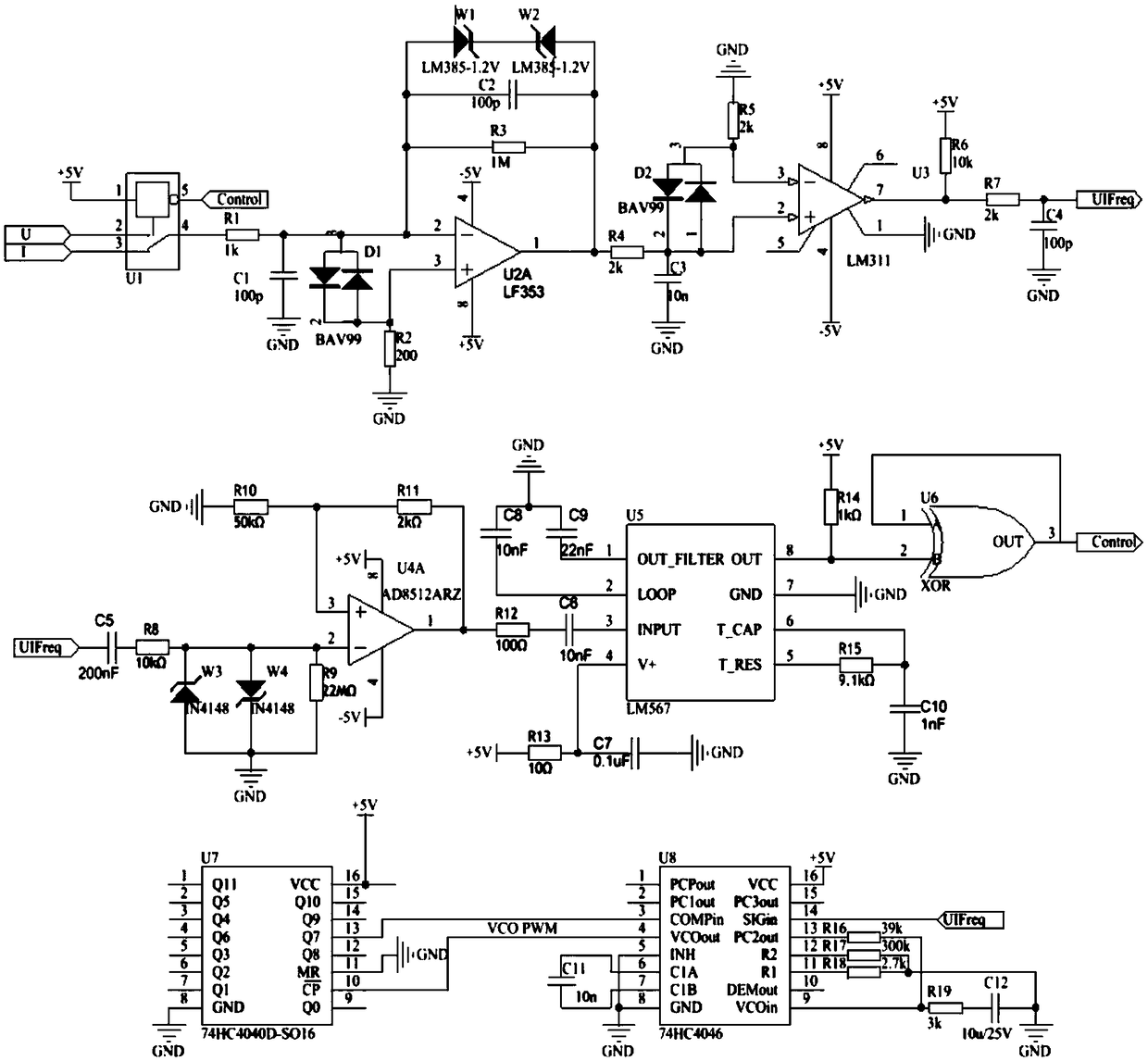
[0023] Such as figure 1 Shown is a synchronization source automatic selection circuit for power meters, including power supply, external voltage input signal, external current input signal, channel selection circuit, input signal frequency conditioning circuit, phase-locked loop frequency multiplication circuit, input signal detection circuit , Channel switching control circuit. The external voltage input signal and the external current input signal are connected to the input end of the channel selection circuit; the output end of the channel selection circuit is connected to the input end of the input signal frequency condit...


PUM


Abstract

The invention relates to a synchronous source automatic selection circuit for a power meter. The synchronous source automatic selection circuit for the power meter comprises a power supply, an external voltage input signal, an external current input signal, a channel selection circuit, an input signal frequency regulating circuit, a phase-locked loop frequency multiplier circuit, an input signal detection circuit and a channel switching control circuit. Whether the input channel signals exist or not is judged through output level signals of a frequency selective network; the output level signal and the logical gate circuit phase calculation is used for realizing the fast, accurate and real-time control of a channel selection analog switch, so that the automatic switching and detection on the voltage channel and current channel can be realized in a hardware mode; the problems of software operation instability, not timely ADC sampling triggering and the like due to voltage channel and current channel control realization by using a conventional software mode are solved; meanwhile, the goal of automatically and preferably selecting channel signals with small distortion and stable waveform to be used as input signals of the PLL phase-locked loop can be achieved; the efficiency and accuracy of the digital power meter measuring are improved to a certain degree.

Description

technical field [0001] The invention relates to the field of electronic measurement, in particular to a synchronous source automatic selection circuit for a power meter. Background technique [0002] With the rapid development of the modern power electronics industry, there are more and more power supply and load products. Most power electronic systems are inseparable from power supply and load. Due to the conversion efficiency of power supply, load power consumption and other related issues directly affect related products. The performance of these systems requires special measuring instruments to detect the energy consumption of these systems. Therefore, there is an increased demand for home appliance manufacturers to use digital power meters to test power supply products and home appliances; the speed requirements for digital power meters to detect products also further improved. [0003] The digital power meter needs to sample the instantaneous value of the input voltag...

Claims


Application Information

Patent Timeline
Patent Type & Authority Applications(China)
IPC IPC(8): G01R22/10
CPCG01R22/10
Inventor 赵浩华陈乐乐
Owner CHANGZHOU TONGHUI ELECTRONICS
Why Eureka
Try Eureka