Mobile hot wedge welder, hot wedge and welding method

A technology of automatic device and hot wedge, applied in movable hot wedge welding automatic device, hot wedge and welding field, can solve the problem of impossible welding speed, and achieve the effect of simplified operation, less noise and slow welding speed

Active Publication Date: 2018-10-16
LEISTER TECHNOLOGIES
View PDF6 Cites 0 Cited by
  • Summary
  • Abstract
  • Description
  • Claims
  • Application Information

AI Technical Summary

Problems solved by technology

However, such welding speeds are not possible with a mobile thermal wedge welding robot and can at best be used in a static, fully automatic welding attachment

Method used


Image

  • Mobile hot wedge welder, hot wedge and welding method
  • Mobile hot wedge welder, hot wedge and welding method
  • Mobile hot wedge welder, hot wedge and welding method

Examples


Embodiment Construction

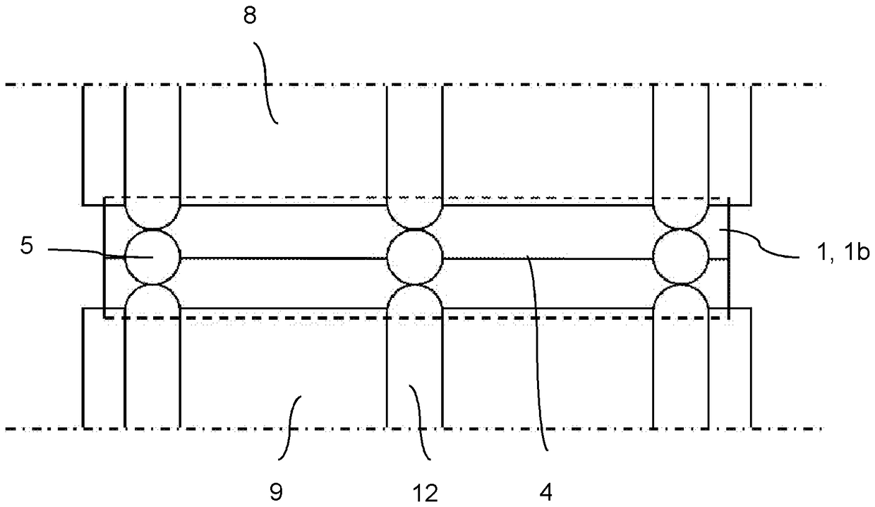
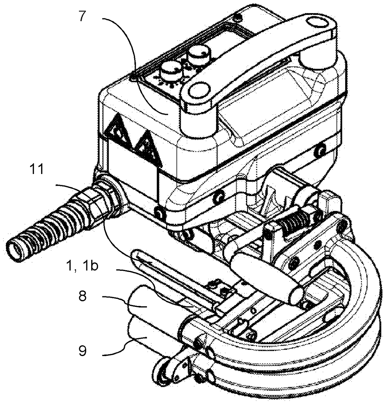
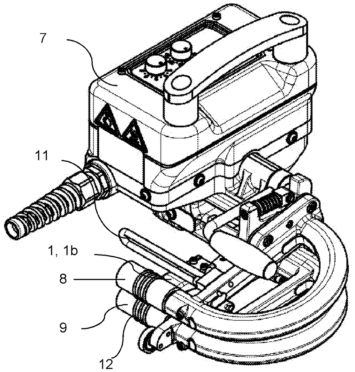
[0027] figure 1 A thermal wedge 1 is shown in different embodiments. All thermal wedges 1 have an upper guide surface 2 as well as a lower guide surface 3 not visible in the figures, said upper and lower guide surfaces, especially in the front region near the thermal wedge tip 4, usually in contact with the The plastic film comes into thermal contact. The connection surface 13 is used for electrical and mechanical contacting of the thermal wedge 1 with a welding device or a welding robot. The thermal wedges 1 a and 1 b have two or three contact elements 5 on the thermal wedge tip 4 , which are designed as thermal wedge lugs connected to the thermal wedge tip 4 with balls at the end. During soldering, the contact element 5 is thermally contacted both by the lower plastic film and by the upper plastic film. The spherical contact element projection 5 therefore has a radius both in the transverse direction and in the longitudinal direction of the thermal wedge and thus brings a...


PUM

PropertyMeasurementUnit
thicknessaaaaaaaaaa
lengthaaaaaaaaaa

Abstract

The invention relates to a hot wedge (1) for a hot wedge welder (7) with an upper guide surface (2) and a lower guide surface (3) and a hot wedge tip (4) with at least one contact element (5, 6) in the region of hot wedge tip (4) for thermal contacting of upper and lower films along a fraction of the length and width of the hot wedge. A mobile hot wedge welder (7) with at least one upper and at least one lower pressure roller (8, 9) has such a hot wedge (1). According to the method, thin plastic films can be welded with a thickness of less than 1 mm by means of the mobile hot wedge welder (7),wherein the plastic films are guided by at least one hot wedge (1); the plastic films contact thermally at least once with the hot wedge over a fraction of the width of the hot wedge, so that at least one weld seam extending in the direction of movement of the plastic films is formed by the hot wedge (1) according to the width of the thermal contact surface.

Description

technical field [0001] The invention relates to a hot wedge for a hot wedge welding robot, a movable hot wedge welding robot and a method for welding thin plastic films, said hot wedge having an upper guide surface for applying the film and a Based on the lower guide surface of the lower film and the tip of the hot wedge, the movable hot wedge welding automatic device is used to use at least one hot wedge with at least one upper pinch roller and at least one lower pinch roller at least on the at least one hot The plastic film is welded in the thermal contact area of ​​the wedge. Background technique [0002] A hot wedge for welding plastic foils and plastic rails is disclosed, in particular by means of a movable hot wedge welding robot. The thermal wedge is utilized so that the plastic film and the plastic rail placed one above the other (upper and lower film) heat the plastic film and the plastic rail during the movement of the thermal wedge fixed on a movable thermal wedg...

Claims


Application Information

Patent Timeline
Patent Type & Authority Applications(China)
IPC IPC(8): B29C65/24
CPCB29C65/242B29C65/20B29C66/1122B29C66/232B29C66/3472B29C66/43B29C66/7352B29C66/73921B29C66/81422B29C66/81427B29C66/8362B29C66/861B29C66/86523
Inventor A.克里斯滕B.冯威尔
Owner LEISTER TECHNOLOGIES
Why Eureka
Try Eureka