Light guide plate with high light extraction rate, uniform light surface and no visual spots

A technology of light guide plate and light output rate, applied in the field of light guide plate, can solve the problems of uneven light, affect the light output rate, low light output rate, etc., and achieve the effect of not affecting the light output rate, uniform smooth surface, and high light output rate

Inactive Publication Date: 2018-10-09
JIANGSU SUN & MOON LIGHTING
View PDF9 Cites 0 Cited by
  • Summary
  • Abstract
  • Description
  • Claims
  • Application Information

AI Technical Summary

Problems solved by technology

The light emitting surface (exiting surface) of the light guide plate with the traditional structure is often adhered to dust. Therefore, after the lamp is turned on, the light emitting surface (exiting surface) is observed, and small white spots, bright spots, spots, etc. often appear, resulting in a uniform light surface. , not only affects the appearance, but also affects the light output rate
In addition, because the existing light guide plate gaps are of the same size, and the light is continuously scattered on the dots on the propagation path, the luminous flux in the direction of the symmetrical centerline of the light guide plate is gradually attenuated, so that the light output rate is low and The emitted light is not uniform

Method used


Image

  • Light guide plate with high light extraction rate, uniform light surface and no visual spots
  • Light guide plate with high light extraction rate, uniform light surface and no visual spots
  • Light guide plate with high light extraction rate, uniform light surface and no visual spots

Examples


Embodiment Construction

[0018] The present invention is described in further detail now in conjunction with accompanying drawing. These drawings are all simplified schematic diagrams, and only illustrate the basic structure of the present invention in a schematic manner, so they only show the configurations related to the present invention.

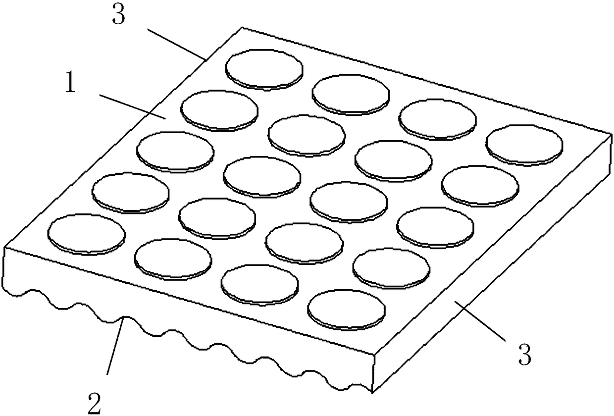
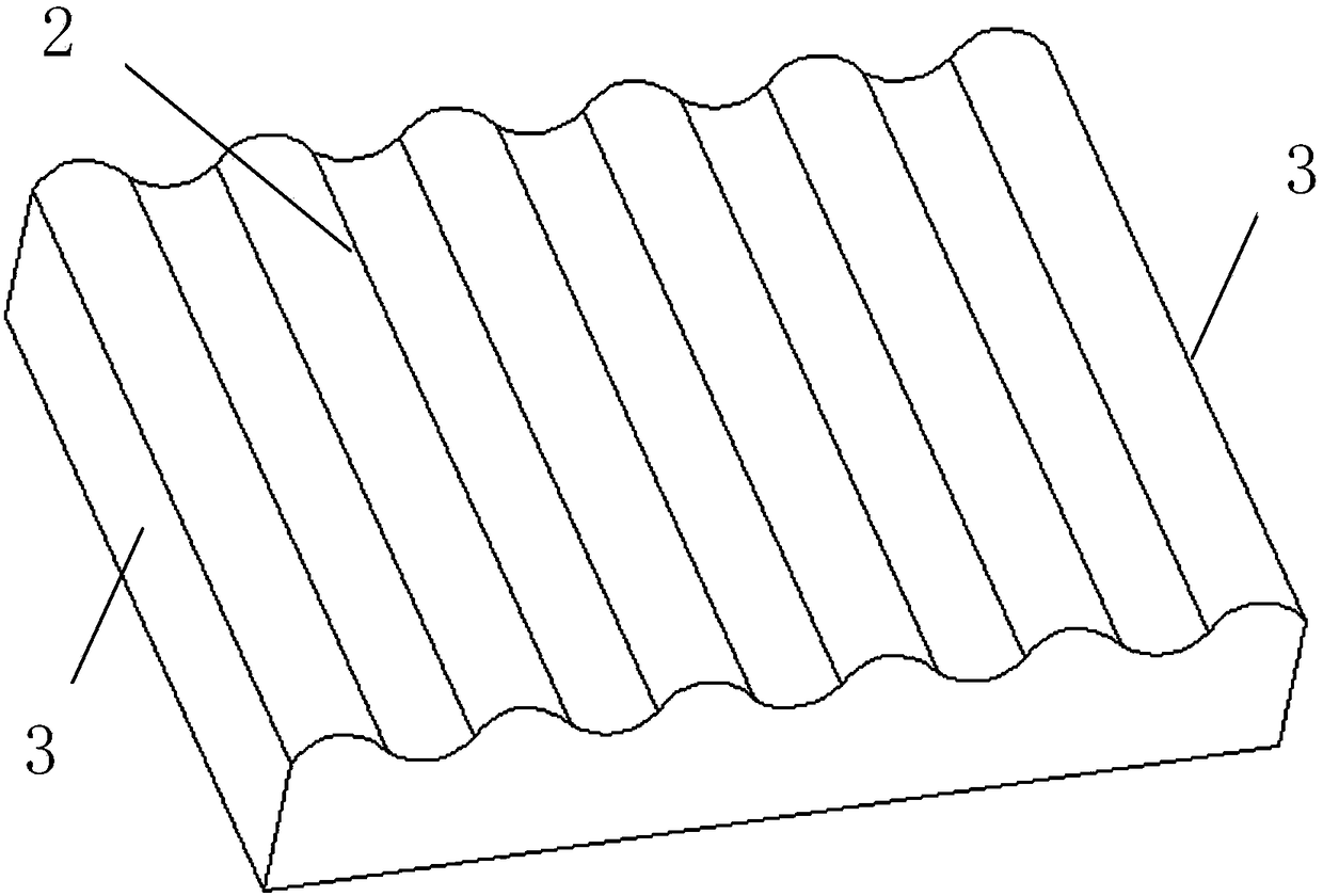
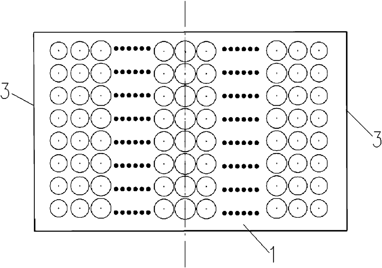
[0019] Such as Figure 1-Figure 3 Shown is a specific embodiment of a light guide plate of the present invention with a high light extraction rate, uniform light surface, and no visual spots, which includes a light guide plate, a pair of opposite sides of the light guide plate are light source sides 3, and the scattering of the light guide plate The surface is a smooth surface 1 and is densely covered with a plurality of dots. The exit surface of the light guide plate is an undulating surface 2 that periodically undulates in the shape of a cos curve. The two light source sides 3 are located at both ends of the undulating surface 2 in the undulating direction; on...


PUM


Abstract

The invention belongs to the technical field of light guide plates and particularly relates to a light guide plate with a high light extraction rate, a uniform light surface and no visual spots. Two opposite edges of a light guide plate are light source sides, a scattering surface of the light guide plate is a smooth surface with the dense distribution of a plurality of dots, an emission surface of the light guide plate is an undulating surface which is periodically curved in a cos curve, and the two light source sides are at two ends of the undulating surface in an undulating direction. The distances between adjacent dots in a light incident direction on two sides are gradually reduced from the two light source sides to the center line of the light guide plate. The light guide plate has the advantages that even if dust adheres to the undulating surface of the light guide plate, white spots, bright spots, spots and the like on the undulating surface are not observed, the appearance ofa lamp is ensured, the light emitting rate is not affected, the dot density are increased to the center from two sides, the scattering areas of the dots are greatly increased, thus the light emittingrate is high, and the emitted light is very uniform.

Description

technical field [0001] The invention belongs to the technical field of light guide plates, and in particular relates to a light guide plate with high light extraction rate, uniform light surface and no visual spots. Background technique [0002] The light guide plate is the key optical device of the flat panel light. Its function is to guide the light emitted by the side-emitting light source through the light guide plate, and from the direction of light entering from the side of the light guide plate, through incident, refraction, reflection, diffuse reflection, etc. The light changes multiple times and becomes a straight light relative to the plane of the flat panel light, which emits from the front of the light guide plate, thereby producing lighting functions and illuminating the surrounding environment. In order to realize the light guide function, on one of the two smooth surfaces of the light guide plate, many ink dots are printed by screen printing. These dots are th...

Claims


Application Information

Patent Timeline
Patent Type & Authority Applications(China)
IPC IPC(8): G02B6/00
CPCG02B6/00G02B6/0043
Inventor 徐向阳
Owner JIANGSU SUN & MOON LIGHTING
Why Eureka
Try Eureka