GIS disconnecting switch contact opening and closing state monitoring sensor
A technology of isolating switches and sensors, applied in the field of GIS isolating switches, can solve the problems of low safety, poor reliability, low confirmation efficiency, etc., and achieve the effect of expanding the scattering area
- Summary
- Abstract
- Description
- Claims
- Application Information
AI Technical Summary
Problems solved by technology
Method used
Image
Examples
Embodiment 1
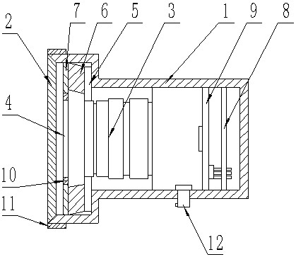
[0024] refer to figure 1 , is a structural schematic diagram of Embodiment 1 of the present invention, a sensor for monitoring the state of opening and closing of GIS isolating switch contacts, including:
[0025] A housing 1, with an opening on one side of the housing 1, and a shielding glass 2 embedded in the opening;
[0026] A collection unit, the collection unit is detachably connected in the casing 1, and the collection end of the collection unit is located on the side of the shielding glass 2;
[0027] A supplementary light unit, the supplementary light unit is arranged in the casing 1 and is located on one side of the shielding glass 2;
[0028] A control unit, the control unit is detachably connected in the casing 1, and the control unit is electrically connected with the supplementary light unit and the acquisition unit.
[0029] In actual use: the shell 1 is connected to the flange of the remote monitoring window of the GIS isolating switch, the shielding glass 2 ...
Embodiment 2
[0031] refer to figure 1 : the acquisition unit includes a lens assembly 3 and a polarizing glass-4, the lens assembly 3 and the polarizing glass-4 are detachably connected in the housing 1, and the polarizing glass-4 is located between the lens assembly 3 and the shielding glass 2 , the supplementary light unit is located at the side of the lens assembly 3 , and the control unit is located at the imaging focus of the lens assembly 3 .
[0032] In actual use: the shielding glass 2 and polarizing glass-4 can effectively eliminate the glare interference of the supplementary light source reflection, the lens assembly 3 can be used to focus, and the high-definition GIS isolating switch contact opening and closing status information can be collected through the lens, which helps to improve The accuracy of cloud analytics.
[0033] In this embodiment, the polarizing glass-4 is an orthogonal polarizing lens.
Embodiment 3
[0035] refer to figure 1 : the supplementary light unit includes an LED lamp 5, a light guide post 6 and a polarizing glass 2 7, the LED lamp 5 is arranged in a ring to form a light ring, the polarizing glass 2 7 and the light guide post 6 are in a ring structure, and the LED The lamp 5 and the polarizing glass 7 are detachably connected to the inner circumferential surface of the housing 1. The light guide column 6 is arranged between the LED lamp 5 and the polarizing glass 7. Both sides of the light guide column 6 are connected to the LED lamp 5 and the polarized light respectively Glass two 7 are bonded together, and one end of the lens assembly 3 is located in the LED lamp 5, and the LED lamp 5 is electrically connected to the control unit.
[0036] In actual use: when monitoring is required, turn on the LED lamp 5, and the LED lamp 5 conducts light guide through the light guide column 6, and then shines into the GIS isolating switch through the polarizing glass 7, the shi...
PUM
 Abstract
Description
Claims
Application Information
 - Generate Ideas
- Intellectual Property
- Life Sciences
- Materials
- Tech Scout
- Unparalleled Data Quality
- Higher Quality Content
- 60% Fewer Hallucinations
Browse by: Latest US Patents, China's latest patents, Technical Efficacy Thesaurus, Application Domain, Technology Topic, Popular Technical Reports.
© 2025 PatSnap. All rights reserved.Legal|Privacy policy|Modern Slavery Act Transparency Statement|Sitemap|About US| Contact US: help@patsnap.com

