


Quick Research
Generate reliable direction feasibility study reports for your R&D in just a few steps.

Technical Q&A
Discover and master advanced knowledge NOW. Basics, ideas, possibilities, all at once.

Find Solutions
As an expert in R&D theories, this can generate solutions to your technical problems instantly.

Evaluate Feasibility
Analyze your overall solution with one click, know your potential R&D risks in advance.

Monitor Landscape
Get weekly tech updates, stay abreast of the latest tech innovations and key insights.
Method for measuring combustion heat release rate in full-scale ventilated confined spaces
A release rate and confined space technology, which is applied in the field of measurement of combustion heat release rate in a full-scale ventilated restricted space, can solve problems such as unreliability and uneven distribution of smoke, and achieve the effect of reducing consumables and simplifying the measurement process
- Summary
- Abstract
- Description
- Claims
- Application Information
AI Technical Summary
Problems solved by technology
Method used
Image

Examples
Embodiment 1
[0061] In this embodiment, a method for measuring the combustion heat release rate in a full-scale ventilated confined space based on the principle of three-layer flue gas partitioning and carbon dioxide generation, the steps are as follows:
[0062] S1: Select indoor flue gas measuring points and arrange flue gas analyzers. Based on the stratification of the flue gas in the three areas, three flue gas analyzer probes are respectively fixed on the upper, middle and lower layers, and the flue gas analyzer probes on the same layer have an appropriate distance;
[0063] S2: Fix the probe of the flue gas analyzer for measuring the concentration of carbon dioxide gas at the exhaust port;
[0064] S3: Debug all flue gas analyzers to synchronize the measurement time and ignite the fire source;
[0065] S4: average the gas concentration data of the indoor flue gas measuring points;
[0066] S5: Calculate the combustion heat release rate based on the principle of carbon dioxide gener...
Embodiment 2
[0085] Present embodiment except following feature other structures are with embodiment 1:
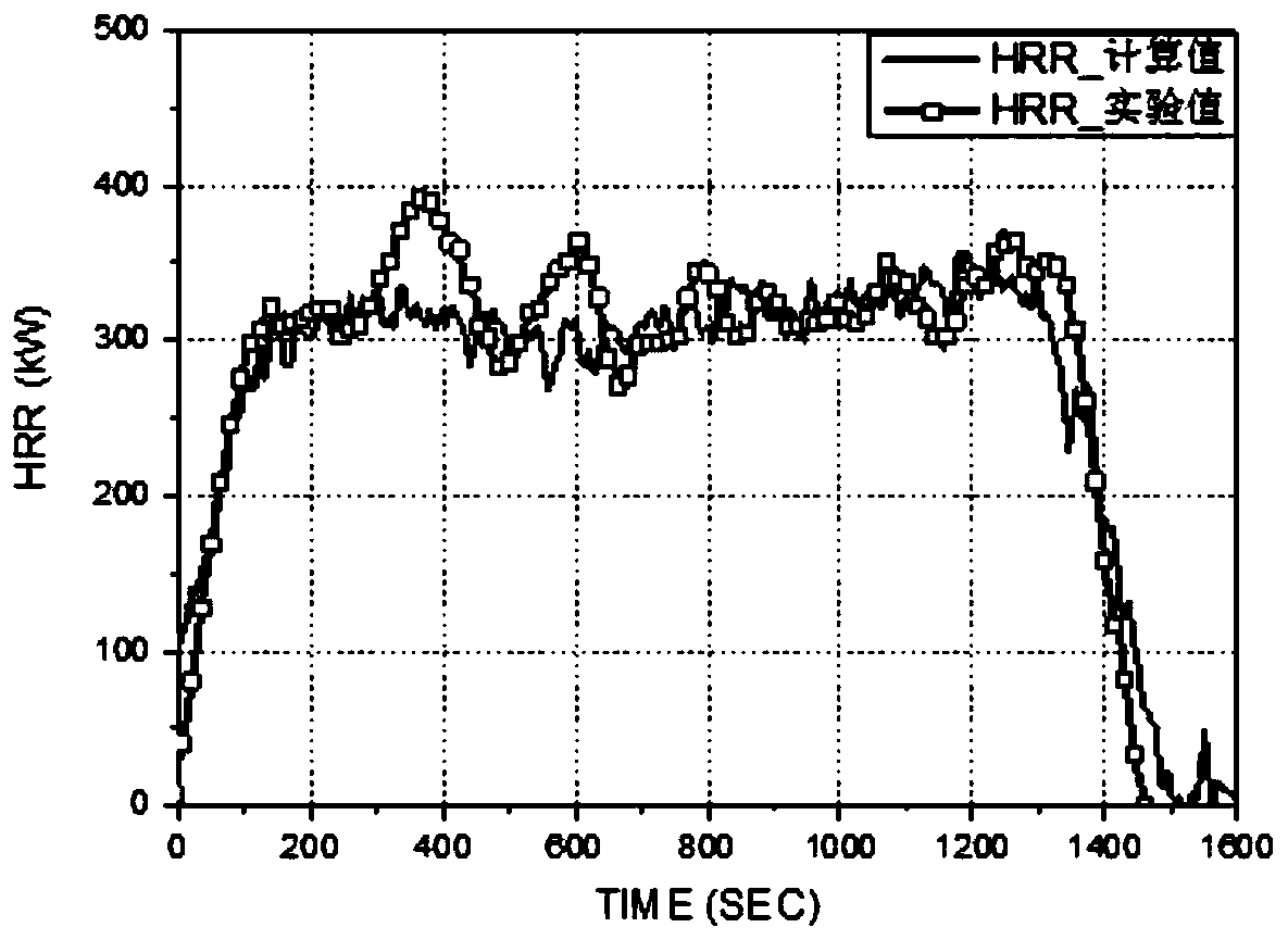
[0086] In this embodiment, the fire source of the combustion test is located in the corner, and the fuel is a heptane oil pool.
[0087] The calculated value of the heat release rate in this embodiment is compared with the experimental value of actual combustion figure 2 shown.
Embodiment 3
[0089] Present embodiment except following feature other structures are with embodiment 1:
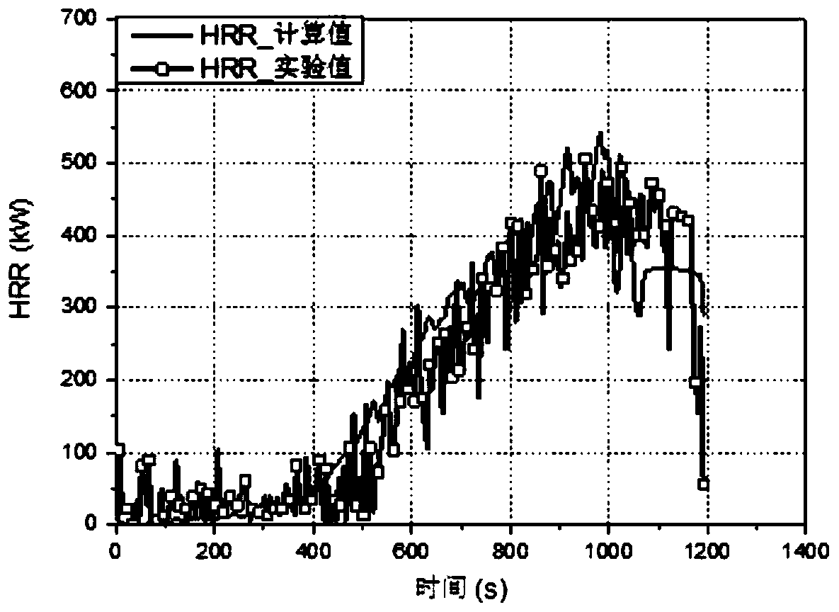
[0090] In this embodiment, the fire source of the combustion test is located near the wall, and the fuel is PMMA solid.
[0091] The calculated value of the heat release rate in this embodiment is compared with the experimental value of actual combustion image 3 shown.
PUM
 Abstract
Description
Claims
Application Information
 - R&D Engineer
- R&D Manager
- IP Professional
- Industry Leading Data Capabilities
- Powerful AI technology
- Patent DNA Extraction
Browse by: Latest US Patents, China's latest patents, Technical Efficacy Thesaurus, Application Domain, Technology Topic, Popular Technical Reports.
© 2024 PatSnap. All rights reserved.Legal|Privacy policy|Modern Slavery Act Transparency Statement|Sitemap|About US| Contact US: help@patsnap.com