An electronically controlled pneumatic brake bridge valve

A pneumatic brake and electronic control technology, applied in the direction of brakes, brake transmissions, vehicle components, etc., can solve the problem of inability to realize real-time and precise control of the brake pressure of a single axle of a vehicle, achieve high integration, improve safety, Guaranteed Effectiveness

Active Publication Date: 2021-03-02
浙江正创科技有限公司 +1
View PDF8 Cites 0 Cited by
  • Summary
  • Abstract
  • Description
  • Claims
  • Application Information

AI Technical Summary

Problems solved by technology

[0005] In short, the problem existing in the existing technology is: when the commercial vehicle is intelligent / unmanned, it is impossible to realize the real-time and precise control of the brake pressure of the single axle of the vehicle

Method used


Image

  • An electronically controlled pneumatic brake bridge valve
  • An electronically controlled pneumatic brake bridge valve
  • An electronically controlled pneumatic brake bridge valve

Examples


Embodiment Construction

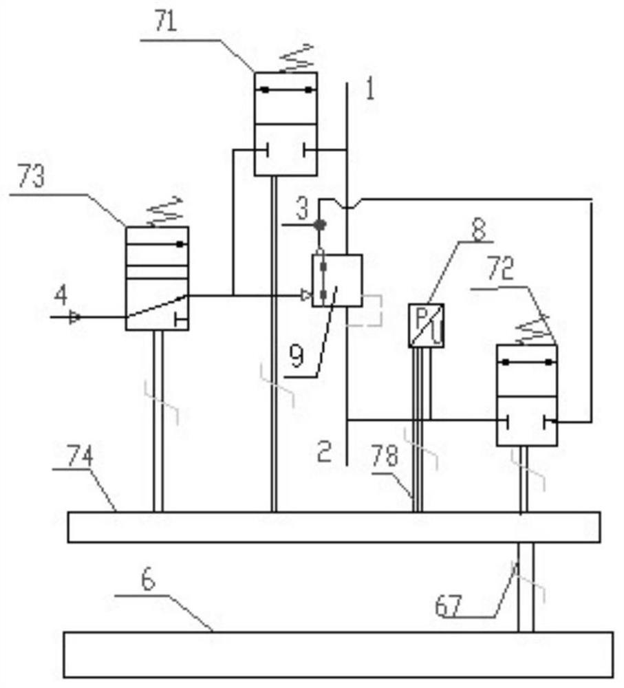
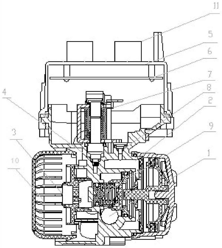
[0020] Such as figure 1 , 2 As shown, the electronically controlled pneumatic brake bridge valve of the present invention includes an air inlet 1, an air outlet 2, an exhaust port 3 and an air pressure control port 4 arranged on the outside of the valve body 5, and the air inlet 1 is used for compressing The air source is connected, the air outlet 2 is used to connect with the intake port of the brake cylinder or ABS valve, the exhaust port 3 is used to connect with the atmosphere, the air pressure control port 4 is used to connect with the pneumatic control valve, and the relay piston 9 controls the intake The connection between gas port 1 and gas outlet 2;

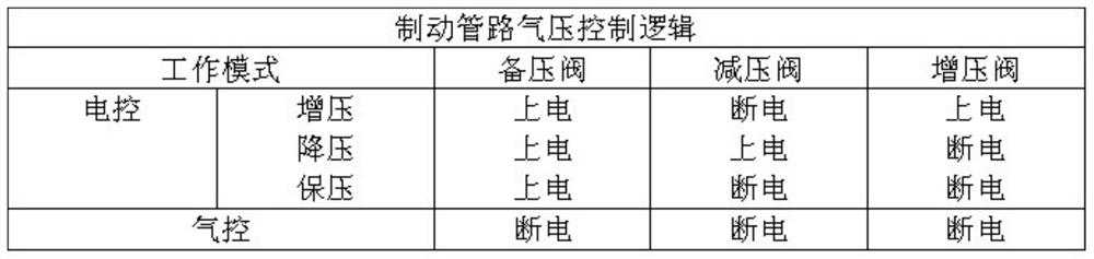
[0021] It also includes the electronic control unit 6 and solenoid valve control board 74 integrated in the top cover of the valve body 5, as well as the pressure boost solenoid valve 71, decompression solenoid valve 72, backup pressure solenoid valve 73 and air pressure sensor 8 placed in the valve body 5 ;

[0022] ...


PUM


Abstract

The invention discloses an electronically controlled pneumatic brake bridge valve, comprising a valve body (5), an air inlet (1), an air outlet (2), an exhaust port (3), an air pressure control port (4) and a relay piston (9), also includes the electronic control unit (6) and solenoid valve control board (74) integrated in the top cover of the valve body (5) and the boost solenoid valve (71) placed in the valve body (5), reducing pressure solenoid valve (72), backup pressure solenoid valve (73) and air pressure sensor (8); one end of the gas circuit of the booster solenoid valve (71) communicates with the air inlet (1), and the other end communicates with the relay piston (9) One end of the gas path of the decompression solenoid valve (72) is connected with the air outlet (2), and the other end is connected with the exhaust port (3); one end of the gas path of the backup pressure solenoid valve (73) is connected with the air pressure control port (4) communicate, and the other end communicates with the control end of relay piston (9). The electronically controlled air brake bridge valve of the present invention has high integration and precise brake air pressure control.

Description

technical field [0001] The invention belongs to the technical field of vehicle braking devices, in particular to an electronically controlled air brake bridge valve capable of precisely controlling the single bridge brake air pressure of an air brake vehicle. Background technique [0002] With the development of smart / autonomous vehicle technology worldwide, more and more commercial vehicles are equipped with driver assistance systems such as automatic emergency braking systems (AEBs), adaptive cruise control (ACC), L2 level and above Automated driving technology has begun to be applied in commercial vehicles. Automated driving technology requires electronic control of the longitudinal dynamics of commercial vehicles, which must be completed by high-performance and reliable electronically controlled air brake actuators. [0003] Existing electronically controlled pneumatic brake actuators mostly use electromagnetic proportional valves and high-speed on-off valves as air pres...

Claims


Application Information

Patent Timeline
Patent Type & Authority Patents(China)
IPC IPC(8): B60T13/68B60T13/26
CPCB60T13/26B60T13/68
Inventor 谢伯元金远波聂石启李春茂李春马江涛
Owner 浙江正创科技有限公司
Why Eureka
Try Eureka