
Reinforced machine tool monitoring system and method based on Internet of Things

A technology of machine tool monitoring and Internet of Things, applied in the field of machinery, can solve problems such as burning, theft, and difficulty in finding routers

Inactive Publication Date: 2018-10-02
时枫娇
View PDF6 Cites 2 Cited by
  • Summary
  • Abstract
  • Description
  • Claims
  • Application Information

AI Technical Summary

Problems solved by technology

[0014] In order to prevent external bumps, the IoT server is installed in a rectangular parallelepiped server case. In order to save indoor space, many server cases are placed outdoors. Due to the increase of heat, the performance of IoT servers is damaged, and there is even a danger of burning. Even though the current server chassis has many cooling holes, its cooling performance is poor. Therefore, for outdoor server chassis, add Equipment that blocks sunlight is the key to urgent treatment
[0015] The data acquisition terminal communicates with the server of the Internet of Things through a router in the Internet of Things; in order to prevent external bumps, the router is arranged in a cuboid router case, and the cover plate hinged on the router case is selected as a general plug. Close the router case, so that the router is only placed in the router case, and the problem of theft often occurs. If it is equipped with an electronic lock, the cost is not low and it is also noticeable. It is often decrypted and opened by the router case. Therefore, the research and development of a class The router chassis with good protection and difficult to find the router is a problem to be dealt with

Method used


Image

  • Reinforced machine tool monitoring system and method based on Internet of Things
  • Reinforced machine tool monitoring system and method based on Internet of Things
  • Reinforced machine tool monitoring system and method based on Internet of Things

Examples


Embodiment Construction

[0068] The present invention will be further described below in conjunction with the drawings and embodiments.

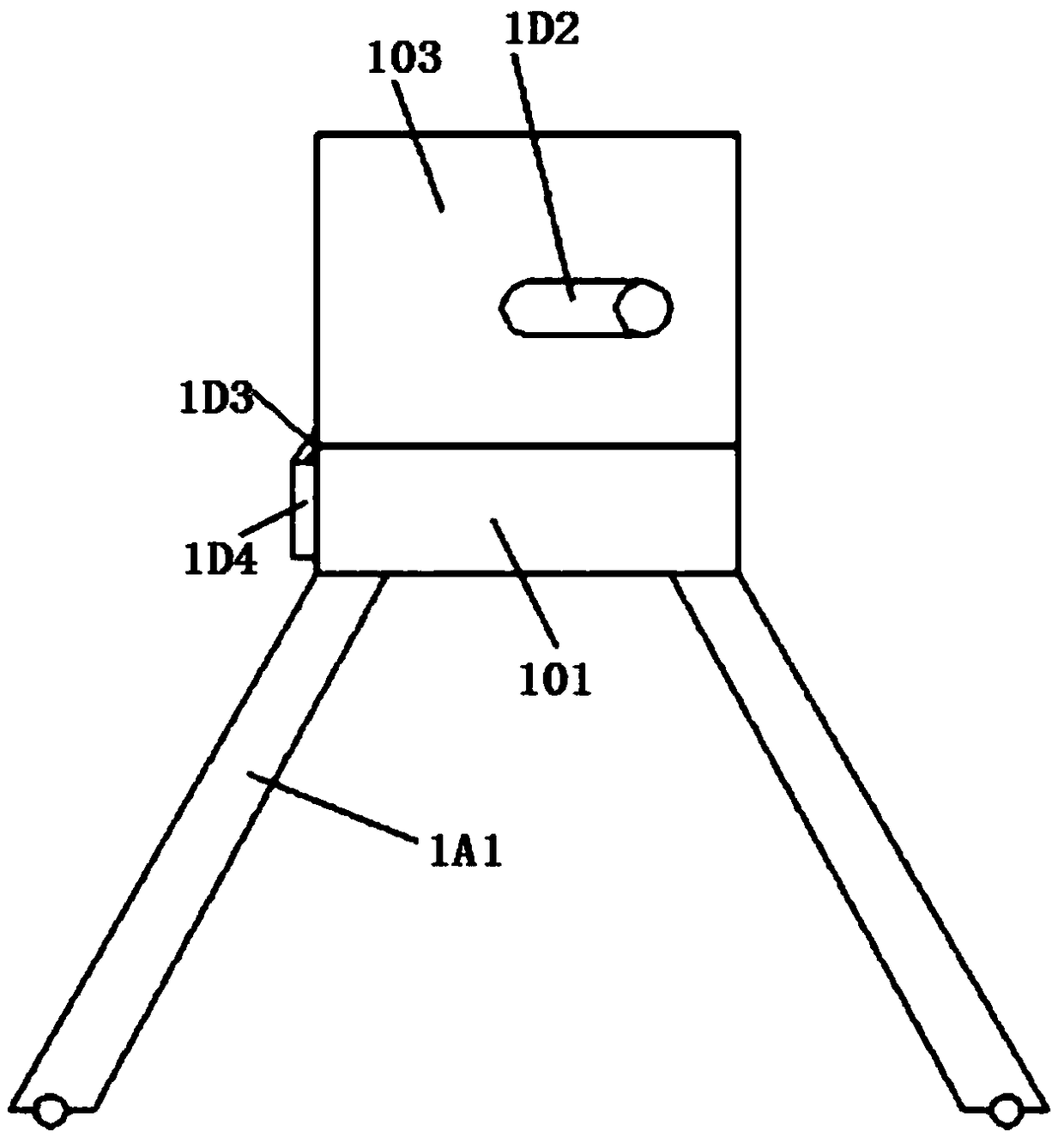
[0069] Such as Figure 1-Figure 24 As shown in the method of an enhanced machine tool monitoring system based on the Internet of Things, the data collection terminal collects the state information data of the CNC machine tool through sensors, and transmits the state information data to the Internet of Things server for storage; The router in the network communicates with the Internet of Things server;

[0070] The Internet of Things server analyzes and responds to the real-time data subscription request sent by the user terminal, extracts data corresponding to the real-time data subscription request from the status information data and sends it to the user terminal for display.

[0071] In addition, for the server case, initially, the telescopic rod 106 is entirely contained in the rectangular parallelepiped supporting frame 103, and the protective cover 1C3 is wrapped ar...


PUM


Abstract

The invention discloses a reinforced machine tool monitoring system and method based on the Internet of Things. A hollow-cuboid-shaped storage shell can be located on a cuboid-shaped vertical sheet ofa box body I by an embedding head, the hollow-cuboid-shaped storage shell is hided behind a cover plate I, and when a background server needs to be taken out from the hollow-cuboid-shaped storage shell, a switch in the cuboid-shaped structure needs to be operated inwards while the neck side of the box body is passed through by a palm; with regard to a server case, firstly, a telescopic roll is accommodated in a cuboid-shaped support frame as a whole, a protection cover is wound on a rotary roll body, and the cuboid-shaped storage shell is also completely accommodated in a guide rail; and thedefects that the performance of an Internet-of-Things server in the server case is influenced and the risk of combustion is caused due to heat increasing, and a router is stolen because of being placed in a router case only, and an electronic lock is decrypted by a person and then the router case is opened in the case that the router case is equipped with the electronic lock, in the prior, are effectively avoided in combination with other steps.

Description

Technical field [0001] The invention relates to the technical field of machinery, in particular to an enhanced machine tool monitoring system and method based on the Internet of Things. Background technique [0002] With the development of industry, the demand for CNC machine tools is getting higher and higher. However, the relative cost of machine tool equipment is relatively high, and with the increase of machine tool equipment, its use efficiency, operating status monitoring, machine tool failure prediction, machine tool resource allocation and other aspects have been greatly challenged. The existing machine tool monitoring is generally It analyzes and monitors machine tools based on collected data manually recorded. When multiple users need to know the status information of different machine tools, its real-time performance cannot meet the rapid development needs of multi-party enterprises. [0003] Thus, there is a monitoring method for CNC machine tools based on the Internet...

Claims


Application Information

Patent Timeline
IPC IPC(8): B23Q15/00B23Q1/00
CPCB23Q1/0045B23Q15/00
Inventor 时枫娇
Owner 时枫娇
Learn More