Tire leakage speed detecting device

A detection device and tire technology, applied in tire measurement, measurement devices, tire parts, etc., can solve problems such as tire burst, slow driving, and unstable vehicle body

Active Publication Date: 2018-09-28
盐城瑞嘉汽车服务有限公司
View PDF8 Cites 0 Cited by
  • Summary
  • Abstract
  • Description
  • Claims
  • Application Information

AI Technical Summary

Problems solved by technology

[0002] Cars are one of the common means of transportation in people's lives. When the car is driving on the road, the tires will inevitably be pressed by some stones or nails, resulting in small holes on the tires, and the gas in the tires leaks out of the small holes. The steering wheel is hard to turn, the body is unstable when driving, and the tires will burst, causing traffic accidents. That is, the tire leaks cannot be ignored; most people find holes in the tires on the road or at home and are leaking. Call the person from the car factory to transport the car or drive to the car factory by yourself. This requires detecting the speed of the air leak. If the speed exceeds a certain value, you can only call the car factory; if the speed is lower than a certain value, the owner can drive slowly to the car factory. factory, can save your own time, and will not cause road congestion. However, most tire leak detection devices in the prior art can only detect whether the tires are leaking, but cannot detect the speed of the leak. It is necessary to design a Detecting device for tire air leakage speed

Method used


Image

  • Tire leakage speed detecting device
  • Tire leakage speed detecting device
  • Tire leakage speed detecting device

Examples


Embodiment Construction

[0017] The present invention will be described in further detail below in conjunction with the embodiments given in the accompanying drawings.

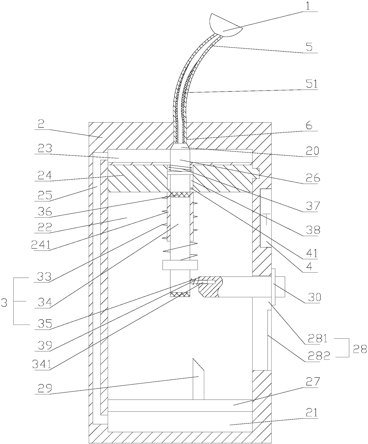
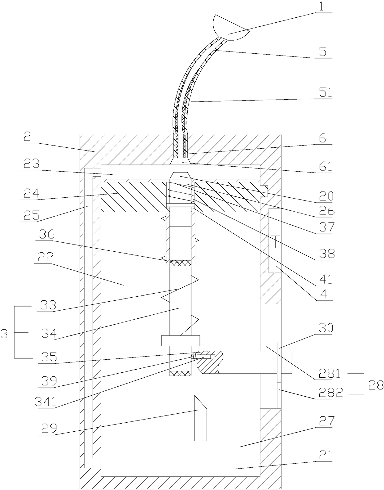
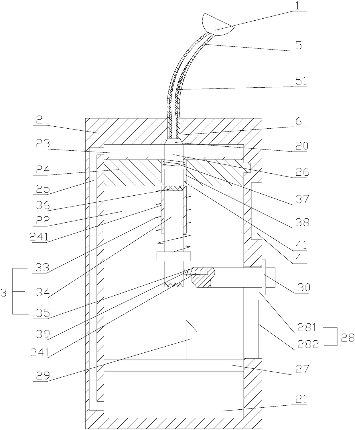
[0018] refer to Figure 1 to Figure 3 As shown, the detection device of a tire air leakage speed in this embodiment includes an air collector 2 and an air nozzle 1 used to connect with the hole on the tire. The air collector 2 is connected to the air nozzle 1 through an air pipe 5, and The interior of the air cylinder 2 is provided with an air collection chamber 21, a sliding chamber 22 and an air intake chamber 23 sequentially along the axial direction of the air collection chamber 2, and a piston plate 27 is arranged between the air collection chamber 21 and the sliding chamber 22, and the piston plate 27 can be relatively assembled. The air cylinder 2 slides, a fixed plate 24 is arranged between the sliding chamber 22 and the air inlet chamber 23, and the air hole 6 communicating with the air supply nozzle 1 and the air inlet chamb...


PUM


Abstract

The invention discloses a tire leakage speed detecting device. According to the technical scheme, the tire leakage speed detecting device comprises an air collection cylinder and an air faucet which is connected with a hole in a tire, wherein the air collection cylinder is connected with the air faucet through an air pipe, and an air collection cavity, a sliding cavity and an air inlet cavity areformed in the air collection cylinder in the axial direction of the air collection cylinder in sequence. A piston plate is slidably arranged between the air collection cavity and the sliding cavity, afixing plate is arranged between the sliding cavity and the air inlet cavity, an air hole is formed in the air collection cylinder, an air channel is formed in the air collection cylinder, a stop block is arranged on the fixing plate, an elastic assembly is arranged in the sliding cavity, and the elastic assembly comprises a direct-stroke push rod, a first spring and a poke rod, wherein the two ends of the first spring are connected with the direct-stroke push rod and the fixing plate respectively, and the direct-stroke push rod is connected with the poke rod through a third spring. A long hole is formed in the air collection cylinder, the poke rod is provided with a limiting disk, the long hole comprises a rod hole body and a disk hole body, a driving rod is arranged on the piston plate,and the end surface, away from the piston rod, of the driving rod is a diagonal plane. The problem that the tire leakage speed cannot be detected is solved.

Description

technical field [0001] The invention relates to a tire detection device, in particular to a tire air leakage speed detection device. Background technique [0002] Cars are one of the common means of transportation in people's lives. When the car is driving on the road, the tires will inevitably be pressed by some stones or nails, resulting in small holes on the tires, and the gas in the tires leaks out of the small holes. The steering wheel is hard to turn, the body is unstable when driving, and the tires will burst, causing traffic accidents. That is, the tire leaks cannot be ignored; most people find holes in the tires on the road or at home and are leaking. Call the person from the car factory to transport the car or drive to the car factory by yourself. This requires detecting the speed of the air leak. If the speed exceeds a certain value, you can only call the car factory; if the speed is lower than a certain value, the owner can drive slowly to the car factory. facto...

Claims


Application Information

Patent Timeline
IPC IPC(8): G01M3/32B60C23/02
CPCB60C23/02G01M3/3254
Inventor 朱丽应沈婷钱瑶瑶李敏惠徐富华金辉
Owner 盐城瑞嘉汽车服务有限公司
Why Eureka
Try Eureka