
Double-layer steel bar mesh machining device

A steel mesh sheet and processing device technology, applied to wire processing, wire mesh, and other household appliances, can solve problems such as large welding quality constraints, large fluctuations in steel bar forming quality, and unstable welding quality, and achieve a reduction in slope. The difficulty of bundling and installing surface steel bars, reducing the number of operators on the warehouse surface, and reducing the effect of safety production risks

Pending Publication Date: 2018-09-28
SINOHYDRO BUREAU 5
View PDF0 Cites 8 Cited by
  • Summary
  • Abstract
  • Description
  • Claims
  • Application Information

AI Technical Summary

Problems solved by technology

[0003] This method uses manual lap welding of steel bar joints. The welding quality is greatly restricted by the welder's technical level and other factors, and the welding quality is unstable; the slope surface performs operations such as welding, erecting, and binding of steel bars, and accurate positioning and installation of steel bars cannot be performed. , the forming quality of steel bars fluctuates greatly; the work tasks on the slope surface are heavy, and there are many personnel and small equipment on the slope surface, and the risk of safety management is relatively high; the traditional process of making face plate reinforcement of face rockfill dams can no longer meet the technical requirements of current face face construction ; can not achieve the purpose of fast, safe and high-quality construction of the face reinforcement of the face rockfill dam; with the rapid development of water conservancy, hydropower and infrastructure construction, the traditional method can no longer solve the increasingly prominent construction period, A series of technical problems such as quality and safety

Method used


Image

  • Double-layer steel bar mesh machining device
  • Double-layer steel bar mesh machining device
  • Double-layer steel bar mesh machining device

Examples


Embodiment Construction

[0031] The present invention will be further described below in conjunction with the accompanying drawings and specific embodiments.

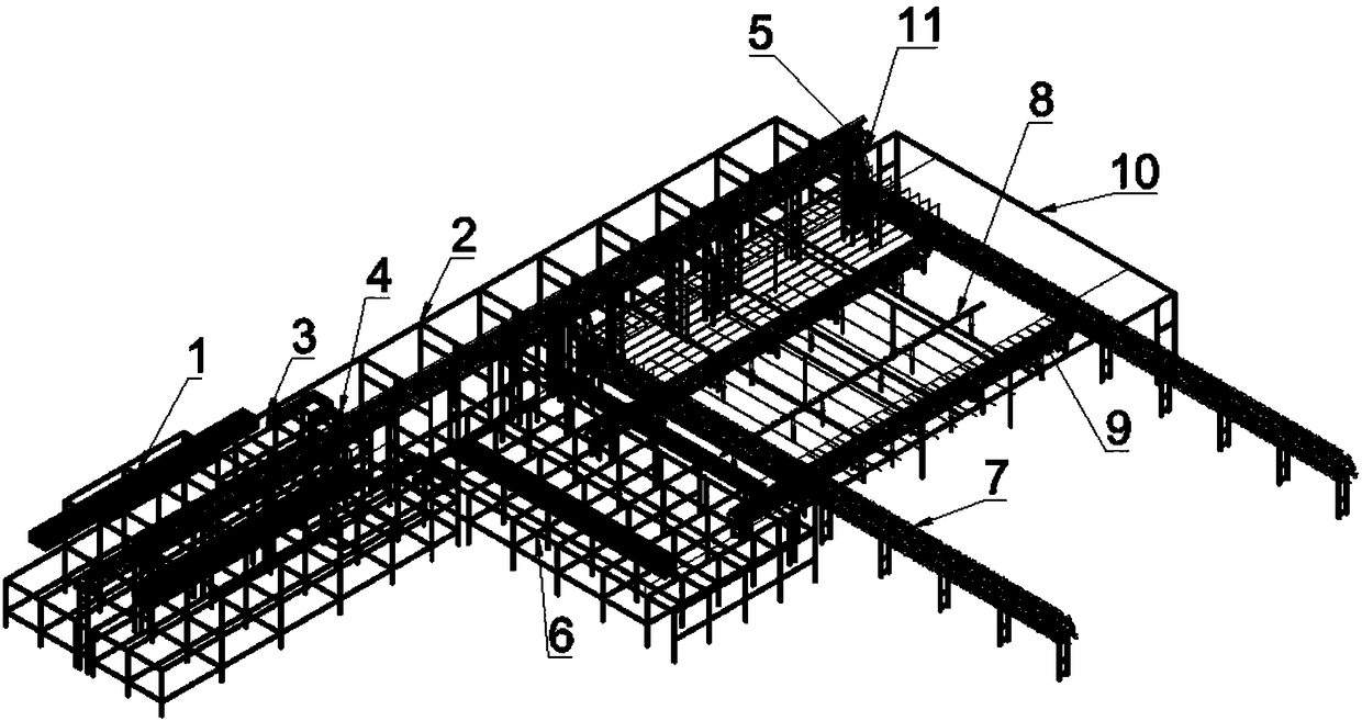
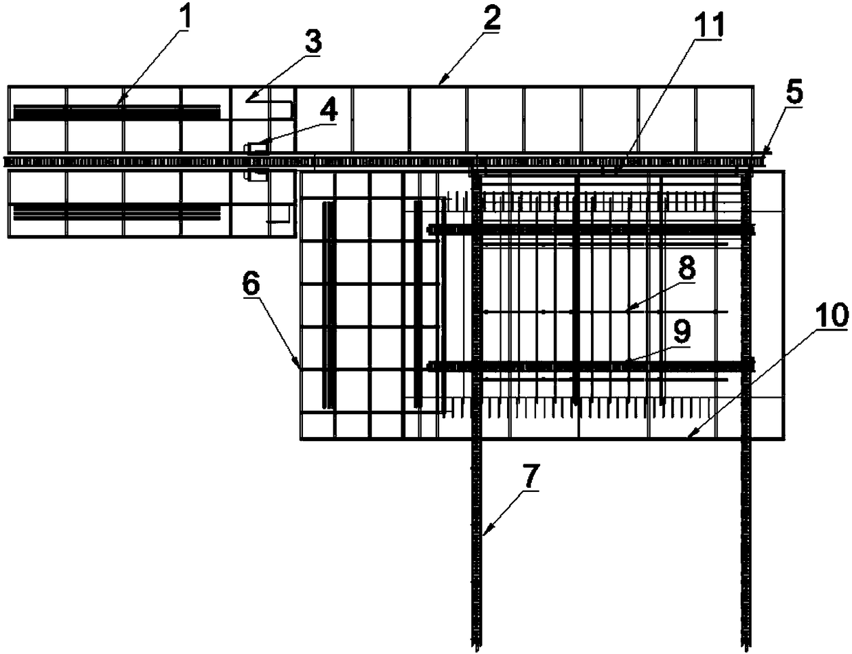
[0032] Such as Figure 1-10 As shown, a double-layer reinforced mesh processing device includes a stirrup conveying device 5, a steel bar erecting device 23 and a flash butt welding machine 4 are arranged at a corresponding position at one end, and a transverse conveying device 7 perpendicular to it is provided at a corresponding position at the other end The stirrup delivery device 5 is provided with a first sliding device 11 for erecting the stirrups from the plane to the vertical direction near the end of the horizontal delivery device 7; The force bar is lifted to the force bar lifting device 8 under the stirrup; it also includes a stacking and distribution platform 10 arranged above the corresponding position of the transverse conveying device 7 for distributing the upper layer of force bar on the upper surface of the stirrup; The tendon ...


PUM


Abstract

The invention discloses a double-layer steel bar mesh machining device. The device comprises a stirrup conveying device, a steel bar erecting device and a flash butt welding machine are arranged at the corresponding positions of one end of the stirrup conveying device, and transverse conveying devices perpendicular to the stirrup conveying device are arranged at the corresponding positions of theother end of the stirrup conveying device; the end, close to the transverse conveying devices, of the stirrup conveying device, is provided with a first sliding device used for vertically erecting stirrups from the plane to the vertical direction; the device further comprises a stress rib jacking device which is arranged at the corresponding positions of the transverse conveying devices and used for jacking distributed lower-layer stress ribs to the positions under the stirrups; and the device further comprises a stacking and distributing platform which is arranged above the corresponding positions of the transverse conveying devices and used for distributing upper-layer stress ribs on the upper surfaces of the stirrups. According to the double-layer steel bar mesh machining device, the construction efficiency is improved, the yield of the steel bar installation quality is improved, the labor cost is reduced, the storehouse surface construction safety is improved, and the safety production risk of slope operation is reduced.

Description

technical field [0001] The invention relates to a mesh processing device, in particular to a mechanized processing device for a double-layer reinforcement mesh used for face reinforcement of face rockfill dams. Background technique [0002] The face plate reinforcement process of face rockfill dams is an important part of quality control, and it is also the key to the progress of face face construction; the traditional construction process mainly includes: firstly, a steel bar processing shed is arranged on the dam surface to bend and shape the steel bars, and then a trolley is used to shape the bars. The semi-finished steel bars are transported to the installation warehouse, and finally the steel bars are welded, bound and erected manually on the slope. [0003] This method uses manual lap welding of steel bar joints. The welding quality is greatly restricted by the welder's technical level and other factors, and the welding quality is unstable; the slope surface performs o...

Claims


Application Information

Patent Timeline
IPC IPC(8): B21F27/10
CPCB21F27/10
Inventor 吴高见李峥巫世奇舒向东刚永才张正勇唐德胜陈洋洋王真平孙晓晓
Owner SINOHYDRO BUREAU 5
Learn More