Stamping trimming mold convenient for converting materials

An edge trimming mold, a convenient technology, applied in the direction of manufacturing tools, machine tools suitable for grinding the edge of workpieces, grinding machines, etc., can solve the problems of affecting work efficiency, unsafe picking, difficult workpiece removal, etc., to improve work efficiency, Improves safety, cutting and edging with good results

Active Publication Date: 2018-09-28
CHUZHOU MODERN MOLD MFG
View PDF7 Cites 0 Cited by
  • Summary
  • Abstract
  • Description
  • Claims
  • Application Information

AI Technical Summary

Problems solved by technology

Among them, the edge trimming process is the process of cutting off the edge material or waste generated during production. It is an indispensable process in all stamping dies. When the existing stamping edge trimming device processes parts, the bottom film often causes the formed parts to be stuck in the cutting process. In the side mold, it is very difficult for the operator to take out the workpiece manually, which seriously affects the work efficiency, and the existing edge trimming mold is directly taken out from the groove, and stamping is a repetitive action. If the staff does not Note that it may lead to insecurity when taking parts, so the present invention proposes a stamping and trimming die with convenient material transfer to solve the above problems

Method used


Image

  • Stamping trimming mold convenient for converting materials
  • Stamping trimming mold convenient for converting materials
  • Stamping trimming mold convenient for converting materials

Examples


Embodiment Construction

[0018] In order to make the purpose, technical solutions and advantages of the embodiments of the present invention clearer, the technical solutions in the embodiments of the present invention will be clearly and completely described below in conjunction with the drawings in the embodiments of the present invention. Obviously, the described embodiments It is a part of embodiments of the present invention, but not all embodiments. Based on the embodiments of the present invention, all other embodiments obtained by persons of ordinary skill in the art without creative efforts fall within the protection scope of the present invention.

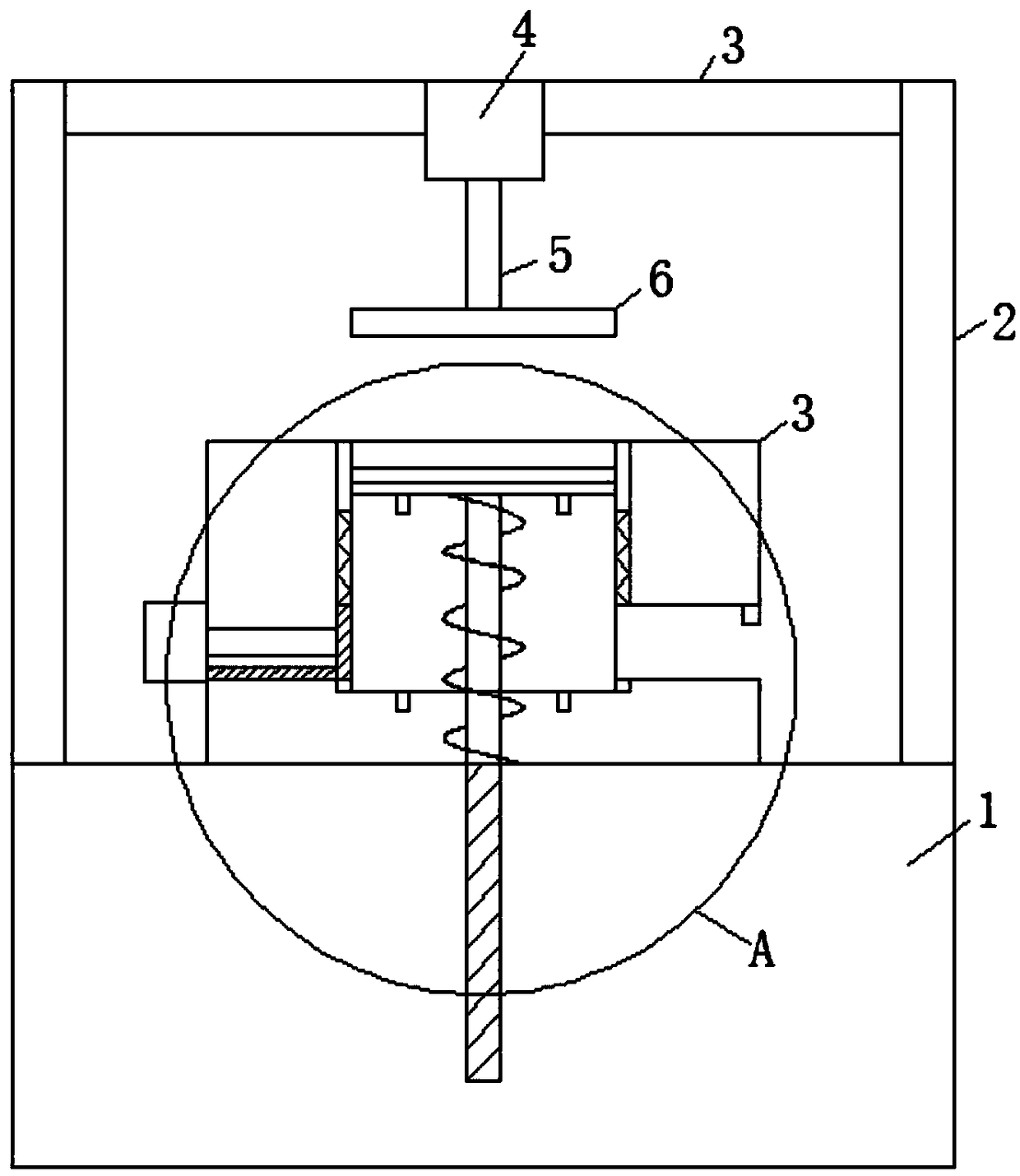
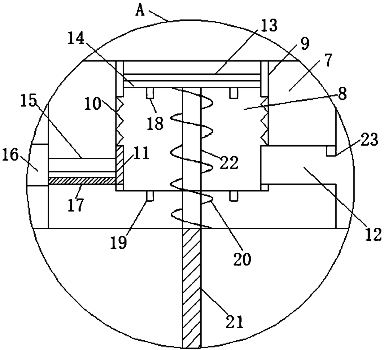
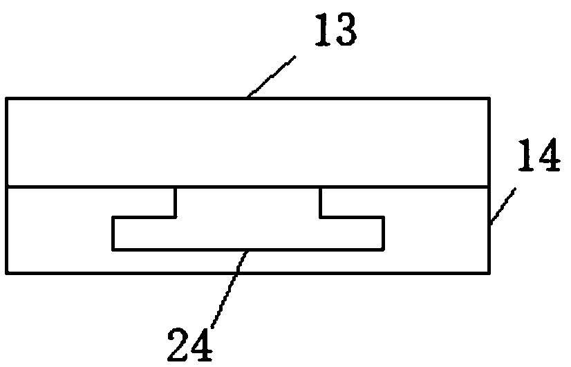
[0019] see Figure 1-4 , the present invention provides a kind of technical scheme: a kind of stamping trimming mold that transfers materials conveniently, comprises workbench 1, upper mold base and lower mold base 3, and workbench 1 is provided with lower mold base 3, and the part of lower mold base 3 Upper upper die base, lower die base 3 compr...


PUM


Abstract

The invention discloses a stamping trimming mold convenient for converting materials. The mold comprises a worktable, an upper mold seat and a lower mold seat, wherein the lower mold seat is arrangedon the worktable, and the upper mold seat is arranged on the lower mold seat; the lower mold seat comprises a substrate, a groove, a pushing device, a supporting plate, a guide bar, a spring and a guide hole; the substrate is arranged on the worktable, the groove is formed in the substrate, the supporting plate is arranged in the groove, the bottom of the supporting plate is connected to the guidebar, the guide bar is inserted into the guide hole, the guide hole is formed in the worktable, a spring I is arranged on the guide bar in a sleeved manner, the pushing device is arranged on one sideof the groove, a discharge groove is formed in the outer side of the groove, an inductor is arranged on the top of the discharge groove, a snap joint is arranged at the lower end of the supporting plate, and a slot matched with the snap joint is formed in the bottom of the groove. The mold disclosed by the invention can trim a workpiece as the lower mold seat is matched with the upper mold seat, and can convert materials for the workpiece by means of the supporting plate matched with the pushing device.

Description

technical field [0001] The invention relates to the technical field of punching edge cutting dies, in particular to a punching edge cutting die with convenient material transfer. Background technique [0002] At present, stamping die is a special process equipment for processing materials (metal or non-metal) into parts (or semi-finished products) in cold stamping processing, called cold stamping die (commonly known as cold stamping die). Stamping is a pressure processing method that uses a mold installed on a press to apply pressure to the material at room temperature to cause separation or plastic deformation to obtain the required parts; generally there are crimping, stretching, bending, Leveling, trimming, blanking, shrinking and other processes. Among them, the edge trimming process is the process of cutting off the edge material or waste generated during production. It is an indispensable process in all stamping dies. When the existing stamping edge trimming device is...

Claims


Application Information

Patent Timeline
Patent Type & Authority Applications(China)
IPC IPC(8): B21D28/14B21D45/02B24B9/04
CPCB21D28/14B21D45/02B24B9/04
Inventor 郭勇朱金枝
Owner CHUZHOU MODERN MOLD MFG
Why Eureka
Try Eureka