
Trestle-type down-hole flow self-adaptive liquid-liquid separation device

A liquid-liquid separation and self-adaptive technology, applied in the direction of production fluid, wellbore/well components, earthwork drilling and production, etc., can solve the limitations of high operating conditions, single operating conditions and scope of application of cyclone separation devices, and inapplicability In order to achieve the effect of simple device structure, efficient separation and good separation performance

Active Publication Date: 2018-09-21
NORTHEAST GASOLINEEUM UNIV
View PDF8 Cites 9 Cited by
  • Summary
  • Abstract
  • Description
  • Claims
  • Application Information

AI Technical Summary

Problems solved by technology

[0004] The purpose of the present invention is to: solve the current cyclone separation device with high requirements on operating conditions, single operating conditions and scope of application; solve the limitation that the specific structure of the cyclone separation device can only handle a single operating parameter, and improve the adaptability of the current separation device Capability and processing accuracy; solve the problem of low separation efficiency of downhole oil-water separation devices due to fluctuation effects such as flow, pressure, and flow velocity, and cannot be applied to the limitations of changing conditions of liquid inflow

Method used


Image

  • Trestle-type down-hole flow self-adaptive liquid-liquid separation device
  • Trestle-type down-hole flow self-adaptive liquid-liquid separation device
  • Trestle-type down-hole flow self-adaptive liquid-liquid separation device

Examples


Embodiment Construction

[0050] The present invention will be further described below in conjunction with accompanying drawing:

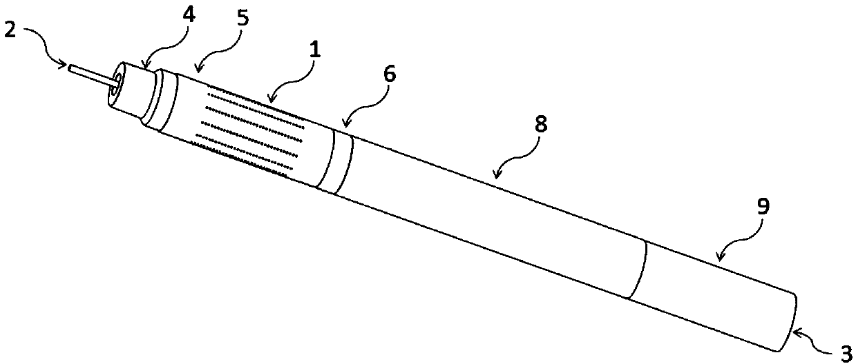
[0051] This trestle type downhole flow self-adaptive liquid-liquid separation device includes a variable diameter joint 4, an inlet pipe 5, a ring type centralizer 6, a trestle type flow stabilization unit 7, a variable diameter separation pipe 8, an overflow pipe 10 and a float type stabilizer. Compressor 9; the top of the overflow pipe 10 is the oil phase outlet 2.

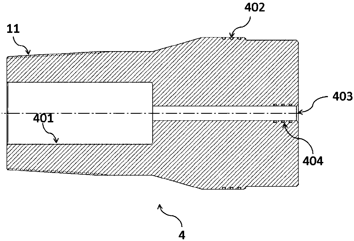
[0052] Among them, the upper end of the variable diameter joint 4 is provided with a pipe taper thread 11 for connecting with the downhole oil pipe, and the lower end is provided with an inlet sealing thread 402 for connecting with the inlet pipe 5, and a through hole is opened in the center, and the overflow pipe 10 runs through this passage. hole; the upper end of the variable diameter joint 4 has an assembly hole 401, and the lower end of the variable diameter joint 4 has a positioning hole 403, and the ov...


PUM


Abstract

The invention relates to a trestle-type down-hole flow self-adaptive liquid-liquid separation device and mainly aims at providing a liquid-liquid separation device. According to the device, by automatically adjusting an internal mechanical structure, the device can adapt to change of the liquid flow rate, and it is achieved and guaranteed that two phases of mediums different in density are efficiently separated in the device. The device is characterized by comprising a diameter-change connector, an inlet pipe, an annular centering device, a trestle-type flow stabilization unit, a diameter-change separation pipe, an overflow pipe and a float-type pressure stabilizer which are connected in sequence; a separation cavity formed by connecting a cylinder-segment rotational flow cavity, a large conical cavity, a small conical cavity and a bottom flow cavity in sequence is formed in the diameter-change separation pipe; the trestle-type flow stabilization unit comprises a flow stabilization sliding block, flow stabilization sheets, flow stabilization connection rods, a flow stabilization spring and a floral-type positioning ring; the overflow pipe penetrates through the trestle-type flow stabilization unit; the trestle-type flow stabilization unit is located in the cylinder-segment rotational flow cavity to form a radial sealing structure between the flow stabilization sheets and the inner wall of a cylinder-segment separation cavity; the float-type pressure stabilizer comprises a rubber float, a pressure stabilization spring and a liquid discharge base.

Description

technical field [0001] The invention relates to a liquid-liquid separation device applied in the fields of petroleum, chemical industry, environmental protection and the like. Background technique [0002] With the continuous development of oil fields, the water content of the produced fluid is gradually increasing, and the cost of crude oil extraction is increasing day by day. At present, my country's main oilfields have entered a period of high water-cut development. Many oilfields have water cuts exceeding 90%, and the comprehensive water cut of Daqing Oilfield has reached 94%. For oil fields with high water cut, the cost of produced water treatment usually accounts for more than 75% of the cost of crude oil production. Due to the energy consumption of raising water from the wellbore to the surface and the increasing cost of water treatment, the production of oil wells reaches the economic limit and is forced to be abandoned. In addition, there are potential environment...

Claims


Application Information

Patent Timeline
Patent Type & Authority Applications(China)
IPC IPC(8): E21B43/38
CPCE21B43/38
Inventor 张勇邢雷陈有斌张艳蒋明虎
Owner NORTHEAST GASOLINEEUM UNIV
Learn More