


Quick Research
Generate reliable direction feasibility study reports for your R&D in just a few steps.

Technical Q&A
Discover and master advanced knowledge NOW. Basics, ideas, possibilities, all at once.

Find Solutions
As an expert in R&D theories, this can generate solutions to your technical problems instantly.

Evaluate Feasibility
Analyze your overall solution with one click, know your potential R&D risks in advance.

Monitor Landscape
Get weekly tech updates, stay abreast of the latest tech innovations and key insights.
Flow measuring device with single measuring tube for nuclear power and mounting method of device
A technology of flow measurement device and installation method, which is applied in the direction of detecting fluid flow by measuring pressure difference, volume/mass flow generated by mechanical effects, etc., can solve problems such as complex processing technology, and achieve simplified processing technology, reduced materials, and installation method simple effect
- Summary
- Abstract
- Description
- Claims
- Application Information
AI Technical Summary
Problems solved by technology
Method used
Image

Examples
Embodiment 1
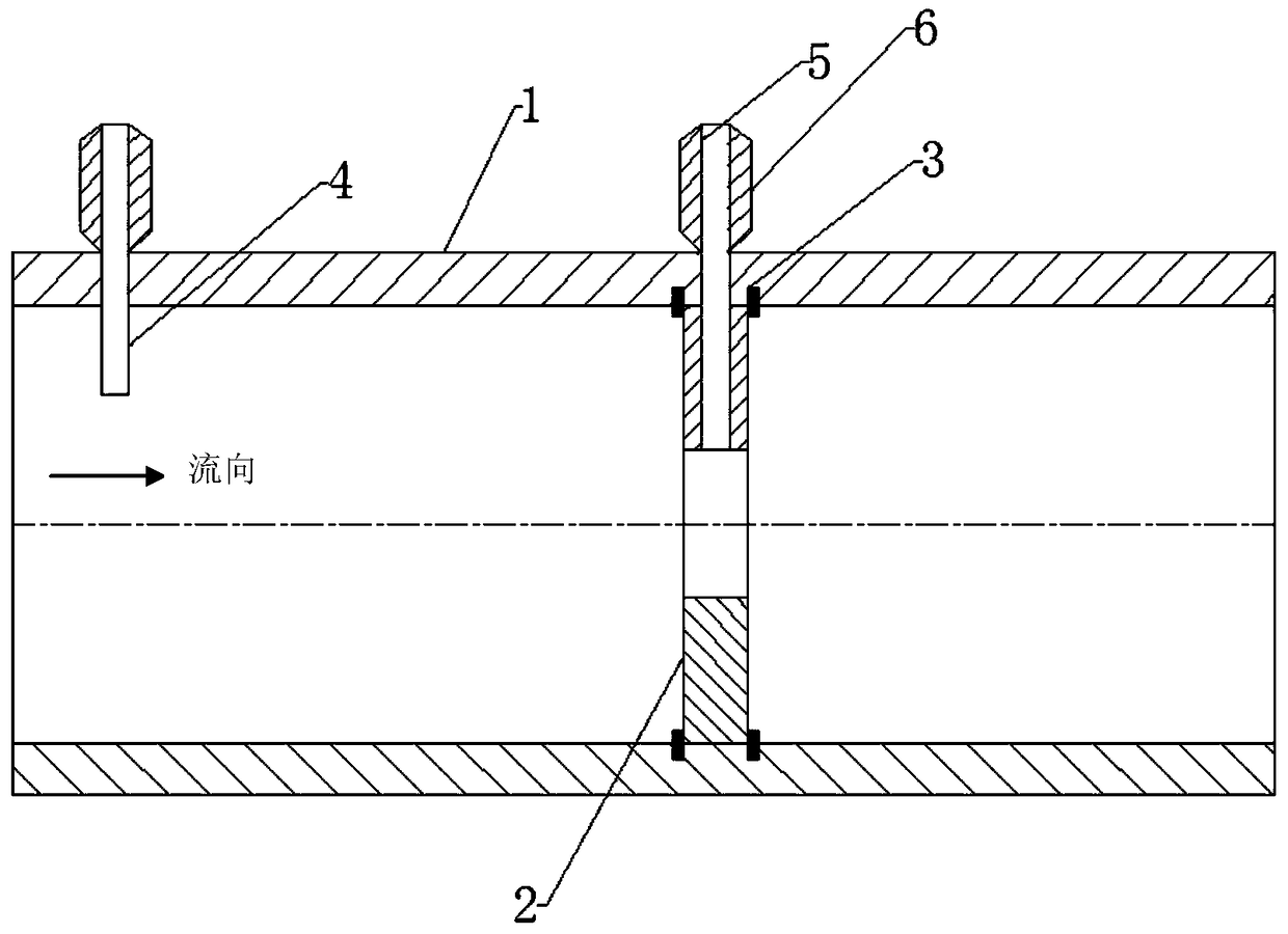
[0029] Such as figure 1 , Figure 4 As shown, in order to simplify the positioning structure of the throttling piece 2, facilitate processing, facilitate the loading and unloading of the throttling piece 2, reduce the leakage of the measuring tube 1, avoid the long-term flow impact of the fluid during use, and make the throttling piece 2 deviate from the position, the preferred The technical solution is that the positioning member 3 is a positioning pin or a positioning screw, and there are at least three positioning pins or positioning screws on each side, which are respectively arranged on both sides of the throttling member 2 and evenly distributed along the circumference. On the inner wall of the measuring tube 1 where the throttling piece 2 needs to be positioned, a blind hole is opened, and the positioning pin or positioning screw is screwed into the blind hole from the inner wall of the measuring tube from the inside to the outside, and the top end protrudes from the in...
Embodiment 2
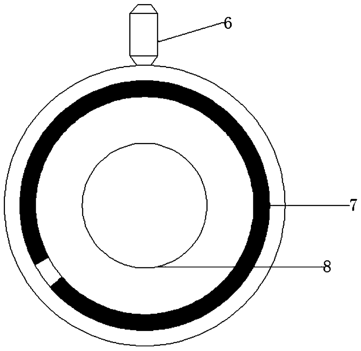
[0031] Such as figure 2As shown, in order to simplify the positioning structure of the throttling piece, facilitate processing, facilitate the loading and unloading of the throttling piece, reduce the leakage of the measuring tube, and avoid the long-term flow impact of the fluid during use, the annular sheet-shaped throttling piece 2 is deviated from the position. The inner wall of the measuring tube 1 is respectively provided with annular grooves on both sides of the installation part of the throttling part 2. The positioning part 3 is made of elastic expansion rings, and the elastic expansion rings are two, which are respectively clamped on the throttle part. 2 In the annular groove on the inner wall of the measuring tube 1 on both sides, when the elastic expansion ring is closed, it is sent into the annular groove from the mouth of the measuring tube. When the elastic expansion ring is loosened, a part is placed in the annular groove, and a part protrudes from the measurem...
Embodiment 3
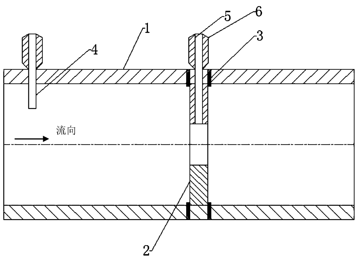
[0033] Such as image 3 As shown, when the pipeline of measuring tube 1 is long or the tube wall is thin or the tube diameter is small, it is inconvenient to open a blind hole from the inner wall of the measuring tube, the positioning part 3 adopts a positioning pin or a positioning screw, and the positioning pin or positioning screw There are at least three on each side, which are respectively arranged on both sides of the throttling member 2 and evenly distributed along the circumference. At the position where the throttling member 2 needs to be positioned on the outer wall of the measuring tube, three through holes are evenly opened along the circumference, and the positioning pin or positioning screw is screwed in through the through hole on the outer wall of the measuring tube 1 and then protrudes from the inner wall of the measuring tube to fix the throttling piece 2. In order to avoid fluid leakage caused by gaps, the outer wall of the measuring tube can be sealed with...
PUM
 Abstract
Description
Claims
Application Information
 - R&D Engineer
- R&D Manager
- IP Professional
- Industry Leading Data Capabilities
- Powerful AI technology
- Patent DNA Extraction
Browse by: Latest US Patents, China's latest patents, Technical Efficacy Thesaurus, Application Domain, Technology Topic, Popular Technical Reports.
© 2024 PatSnap. All rights reserved.Legal|Privacy policy|Modern Slavery Act Transparency Statement|Sitemap|About US| Contact US: help@patsnap.com