
Light reinforced concrete pipe gallery

A reinforced concrete technology, applied in the field of pipe gallery, can solve the problems of affecting the service life of the pipeline, cracking of concrete, and adjusting the size of the fixing frame, etc., and achieve the effect of avoiding concrete cracking, increasing rigidity and increasing service life.

Active Publication Date: 2018-09-14
ANHUI YUTE CONCRETE STRUCTURE TECH
View PDF6 Cites 1 Cited by
  • Summary
  • Abstract
  • Description
  • Claims
  • Application Information

AI Technical Summary

Problems solved by technology

[0002] Pipe gallery, that is, the corridor of pipelines, is composed of columns, beams and trusses of steel structure or reinforced concrete structure. Many pipelines in chemical and related factories are gathered together and arranged along the device or outside the factory building, usually in the In the air, it is supported by brackets to form a similar appearance to the corridor. There are also a few pipe galleries located underground. Most of the existing concrete pipe galleries are not strong enough to be easily cracked by external forces, and the pipes cannot be fixed according to the size of the pipes. The size of the fixing frame makes it impossible to adjust the fixed position of the pipe according to the demand. At the same time, the internal ventilation of the existing pipe gallery is not good, and the humidity of the internal air cannot be detected. Excessive humidity may cause corrosion of the pipe and affect the service life of the pipe.

Method used


Image

  • Light reinforced concrete pipe gallery
  • Light reinforced concrete pipe gallery
  • Light reinforced concrete pipe gallery

Examples


Embodiment Construction

[0014] The following will clearly and completely describe the technical solutions in the embodiments of the present invention with reference to the accompanying drawings in the embodiments of the present invention. Obviously, the described embodiments are only some, not all, embodiments of the present invention. Based on the embodiments of the present invention, all other embodiments obtained by persons of ordinary skill in the art without making creative efforts belong to the protection scope of the present invention.

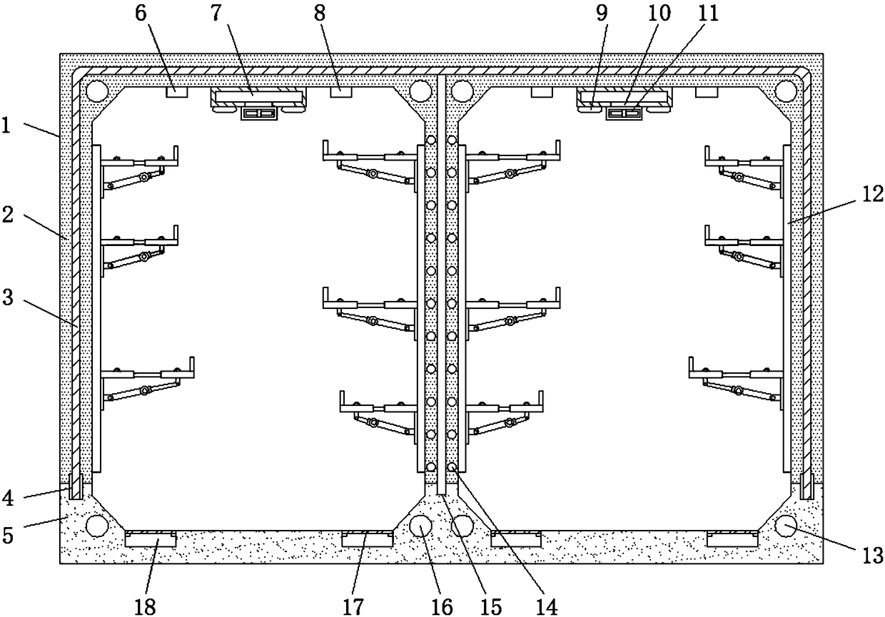
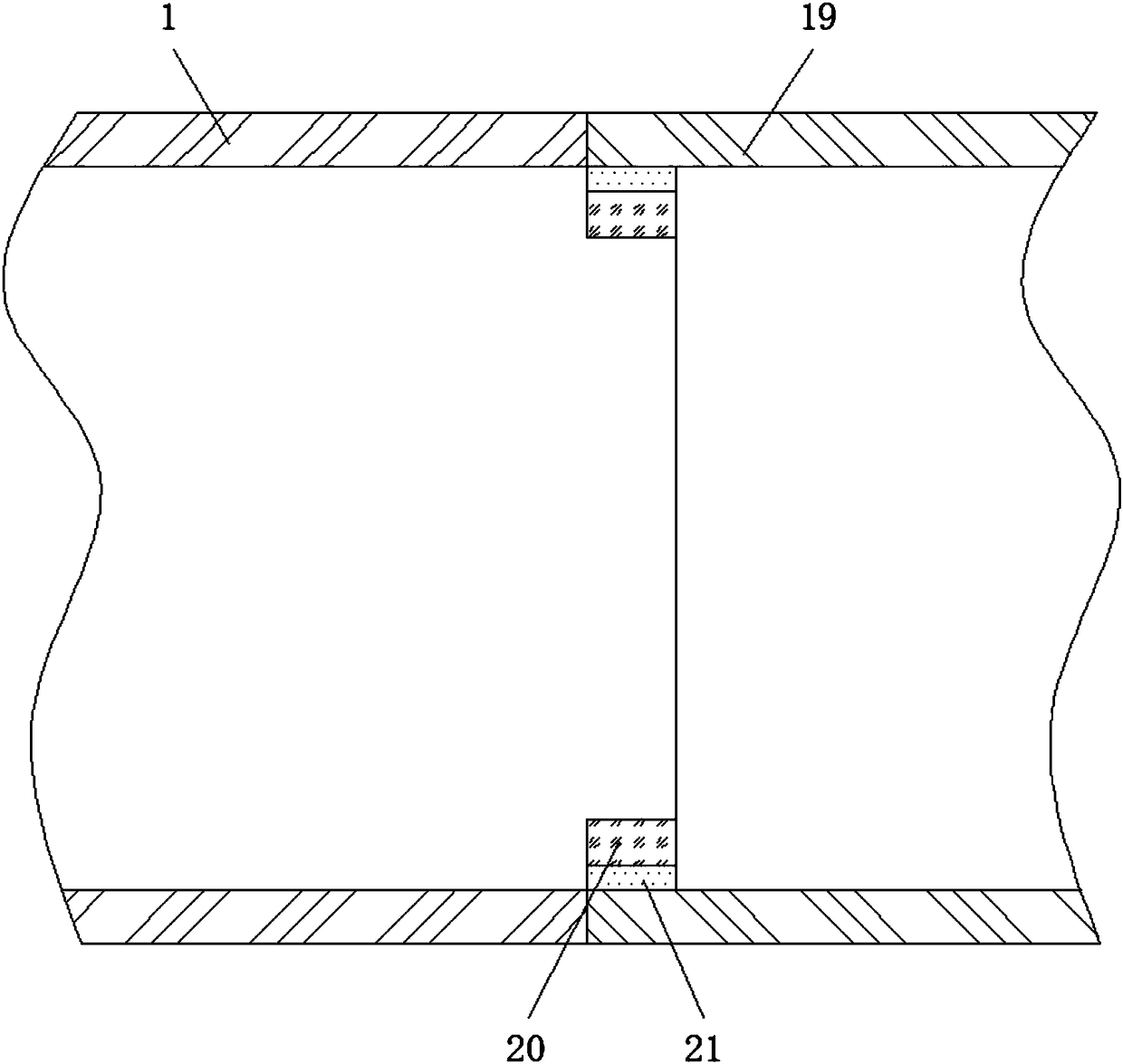
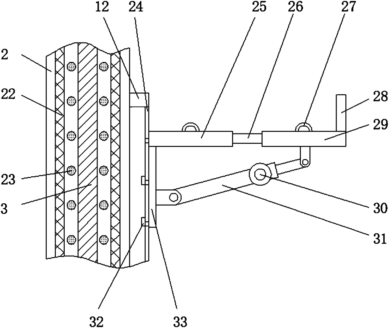
[0015] see Figure 1-3 , an embodiment provided by the present invention: a lightweight reinforced concrete pipe gallery, including a first pipe gallery 1, a concrete wall 2, a base 5 and a second pipe gallery 19, and one side of the first pipe gallery 1 is installed There is a second pipe gallery 19, a sealing ring 20 and a waterstop 21 are respectively installed at the connection between one end of the first pipe gallery 1 and the second pipe gallery 19, and...


PUM


Abstract

The invention discloses a light reinforced concrete pipe gallery which comprises a first pipe gallery, a concrete wall, a base and a second pipe gallery. The second pipe gallery is mounted on one sideof the first pipe gallery. The base is arranged at the bottom end of the first pipe gallery and the bottom end of the second pipe gallery. A partition plate is mounted in the middle of the top of thebase. A water stop baffle is mounted at the top of the partition plate, and the concrete wall is cast at the position, between the water stop baffle and the partition plate, of the top of the base. Air grooves are mounted at the top end in the concrete wall, and a fan is mounted at the bottom of each air groove. According to the light reinforced concrete pipe gallery, through mounting of the first pipe gallery, the concrete wall, the base and the second pipe gallery, first fixed steel bars and second fixed steel bars are evenly mounted in the concrete wall and the base, first reinforcing barsare evenly mounted on the two sides of the partition plate, second reinforcing ribs are evenly mounted on one sides of third reinforcing ribs evenly mounted on the two sides of the water stop baffle,the rigidity and strength of the whole pipe gallery can be increased conveniently, and the situation that concrete cracking is caused due to the fact that the device is affected with external force is avoided.

Description

technical field [0001] The invention relates to the technical field of pipe galleries, in particular to a lightweight reinforced concrete pipe gallery. Background technique [0002] Pipe gallery, that is, the corridor of pipelines, is composed of columns, beams and trusses of steel structure or reinforced concrete structure. Many pipelines in chemical and related factories are gathered together and arranged along the device or outside the factory building, usually in the In the air, it is supported by brackets to form a similar appearance to the corridor. There are also a few pipe galleries located underground. Most of the existing concrete pipe galleries are not strong enough to be easily cracked by external forces, and the pipes cannot be fixed according to the size of the pipes. The size of the fixing frame makes it impossible to adjust the fixed position of the pipe according to the demand. At the same time, the internal ventilation of the existing pipe gallery is not go...

Claims


Application Information

Patent Timeline
Patent Type & Authority Applications(China)
IPC IPC(8): E02D29/045F24F7/007F24F11/89F24F11/70F24F110/20F24F110/50
CPCE02D29/10F24F7/007F24F11/70F24F11/89F24F2110/20F24F2110/50
Inventor 肖吕阳
Owner ANHUI YUTE CONCRETE STRUCTURE TECH
Learn More