Valve element grinding equipment

A kind of equipment and spool technology, which is applied in the field of spool grinding equipment, can solve the problems of excessive grinding time, uncertain spool time, excessive grinding, etc., and achieve the effect of avoiding insufficient grinding, high degree of automation, and ensuring consistency

Inactive Publication Date: 2018-09-07
CHONGQING QIANYAN MACHINERY CO LTD
View PDF5 Cites 4 Cited by
  • Summary
  • Abstract
  • Description
  • Claims
  • Application Information

AI Technical Summary

Problems solved by technology

[0004] The present invention intends to provide a valve core grinding equipment to solve the problem of insufficient grinding and excessive grinding ...

Method used


Image

  • Valve element grinding equipment
  • Valve element grinding equipment
  • Valve element grinding equipment

Examples


Embodiment Construction

[0019] The present invention will be described in further detail below by means of specific embodiments:

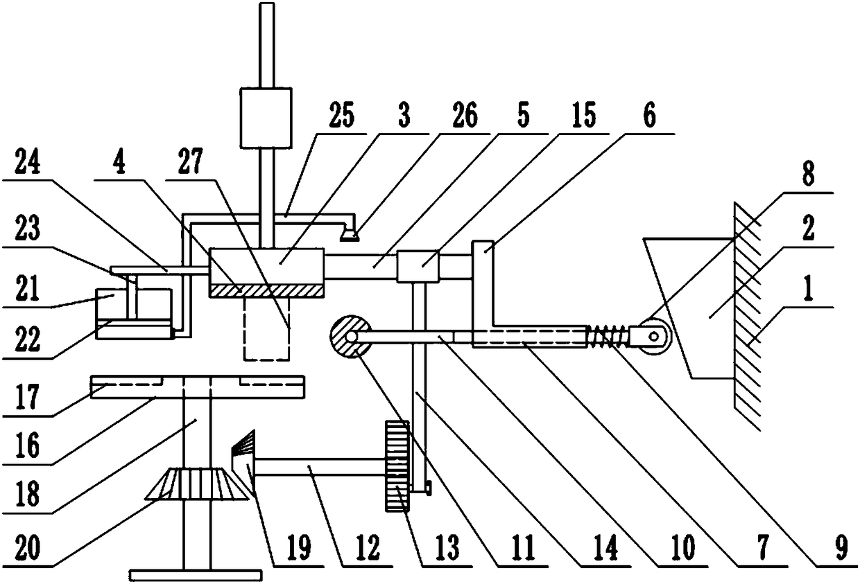
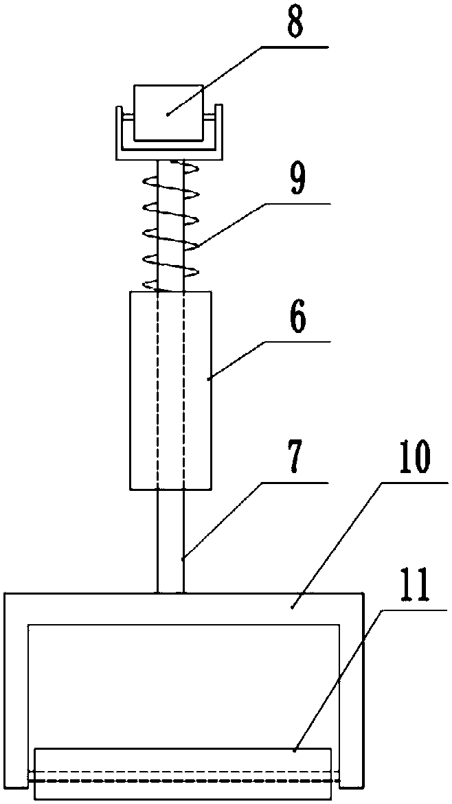
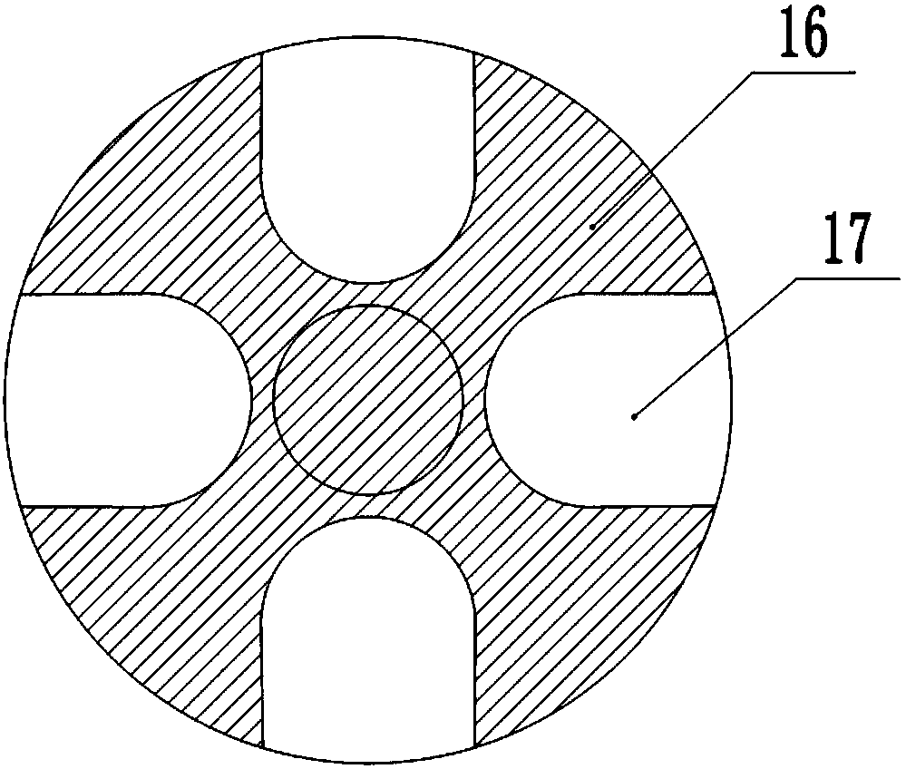
[0020] The reference signs in the accompanying drawings include: frame 1, wedge block 2, fixed plate 3, first magnet 4, first connecting rod 5, L-shaped rod 6, first support rod 7, roller 8, support spring 9 , grinding frame 10, grinding roller 11, drive shaft 12, drive disc 13, drive rod 14, fixed ring 15, transfer disc 16, transfer groove 17, vertical shaft 18, first bevel gear 19, second bevel gear 20, cylinder 21. Sliding plate 22, piston rod 23, cross bar 24, conduit 25, nozzle 26, valve core 27.

[0021] The embodiment is basically as figure 1 , figure 2 Shown: a valve core grinding equipment, including a frame 1 and a grinding mechanism, a wedge block 2 is fixedly connected to the frame 1, the grinding mechanism is located on one side of the wedge block 2, and the grinding mechanism includes a sliding connection on the frame 1 The fixed plate 3, the high end of...


PUM


Abstract

The invention relates to valve element grinding equipment. The valve element grinding equipment comprises a wedge-shaped block and a fixing plate. A first magnet is arranged on the fixing plate. A first connecting rod is fixedly connected with the fixing plate. An L-shaped rod is fixedly connected with the other end of the first connecting rod. A penetrating through hole is formed in the L-shapedrod. A first supporting rod is slidably connected into the through hole. One end of the first supporting rod penetrates through the through hole and is connected with a roller. The roller abuts against the wedge-shaped block. A supporting spring is arranged on the first supporting rod in a sleeving mode. A grinding roller is fixedly connected with the other end of the first supporting rod. A driving shaft is arranged under the grinding roller. A driving plate is fixedly connected with the driving shaft coaxially. A driving rod is rotationally connected with the eccentric position of the driving plate. A first connecting rod is connected with the other end of the driving rod. A first bevel gear is fixedly connected with the driving shaft coaxially and is a sector gear. A transfer plate is arranged under the fixing plate. A vertical shaft is fixedly connected with the transfer plate and coaxially and fixedly connected with a second bevel engaged with the first bevel gear. The grinding time of the equipment is uniform.

Description

technical field [0001] The invention relates to the field of valve processing, in particular to a valve core grinding device. Background technique [0002] A valve is a device used to control the direction, pressure, and flow of a fluid in a fluid system. A valve is a device that makes or stops the flow of media (liquid, gas, powder) in piping and equipment and controls its flow. Valves can be used to control the flow of various types of fluids such as air, water, steam, various corrosive media, mud, oil, liquid metal and radioactive media. The valve is a control component in the pipeline fluid delivery system. It is used to change the passage section and the flow direction of the medium, and has the functions of diversion, cut-off, throttling, check, diversion or overflow relief. [0003] Valves can be divided into: (1) Cut-off categories: such as gate valves, globe valves, plug valves, ball valves, butterfly valves, needle valves, diaphragm valves, etc. (2) Check type: ...

Claims


Application Information

Patent Timeline
IPC IPC(8): B24B15/04B24B55/06B24B41/00B24B41/06B24B47/20B24B47/16
CPCB24B15/04B24B41/005B24B41/06B24B47/16B24B47/20B24B55/06
Inventor 罗贵良
Owner CHONGQING QIANYAN MACHINERY CO LTD
Why Eureka
Try Eureka