Anchoring connection method pulling-resistant device for single pile vertical pulling-resistant static load test
A technology of static load test and connection method, which is applied in the direction of basic structure test, construction, and basic structure engineering, etc. It can solve the problems of long preparation time for connection structures, safety threats at welding places, and long test preparation time, so as to save construction time , save the connection parts, the effect of simple structure
- Summary
- Abstract
- Description
- Claims
- Application Information
AI Technical Summary
Problems solved by technology
Method used
Image
Examples
Embodiment 1
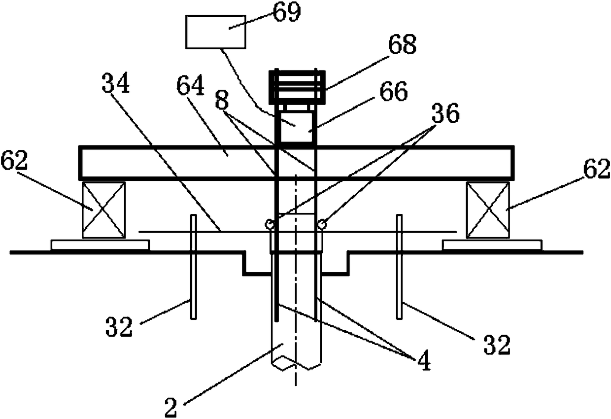
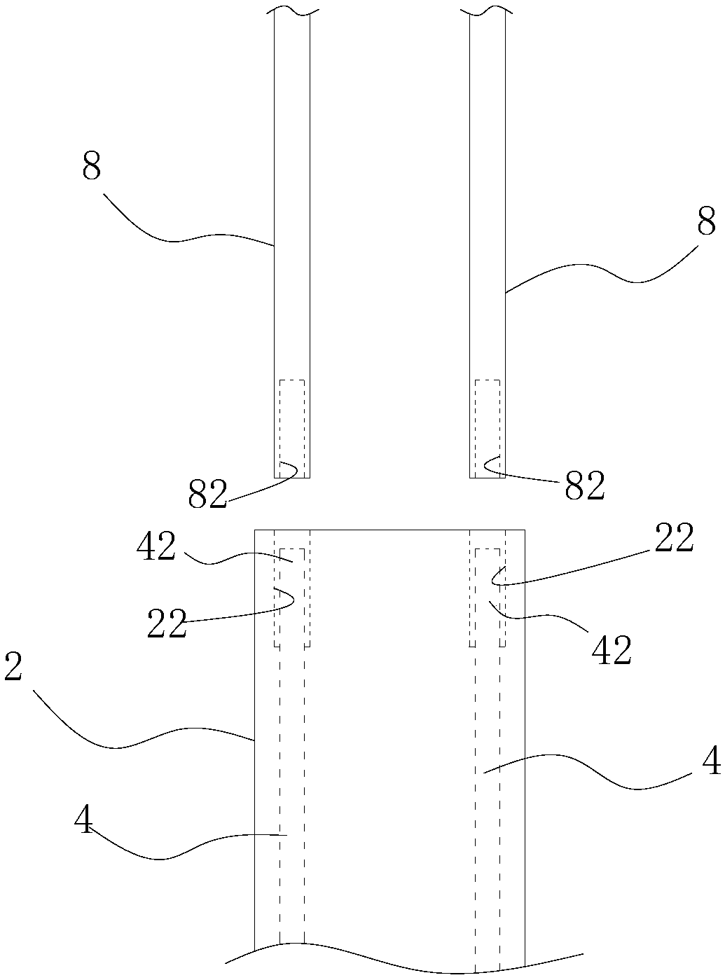
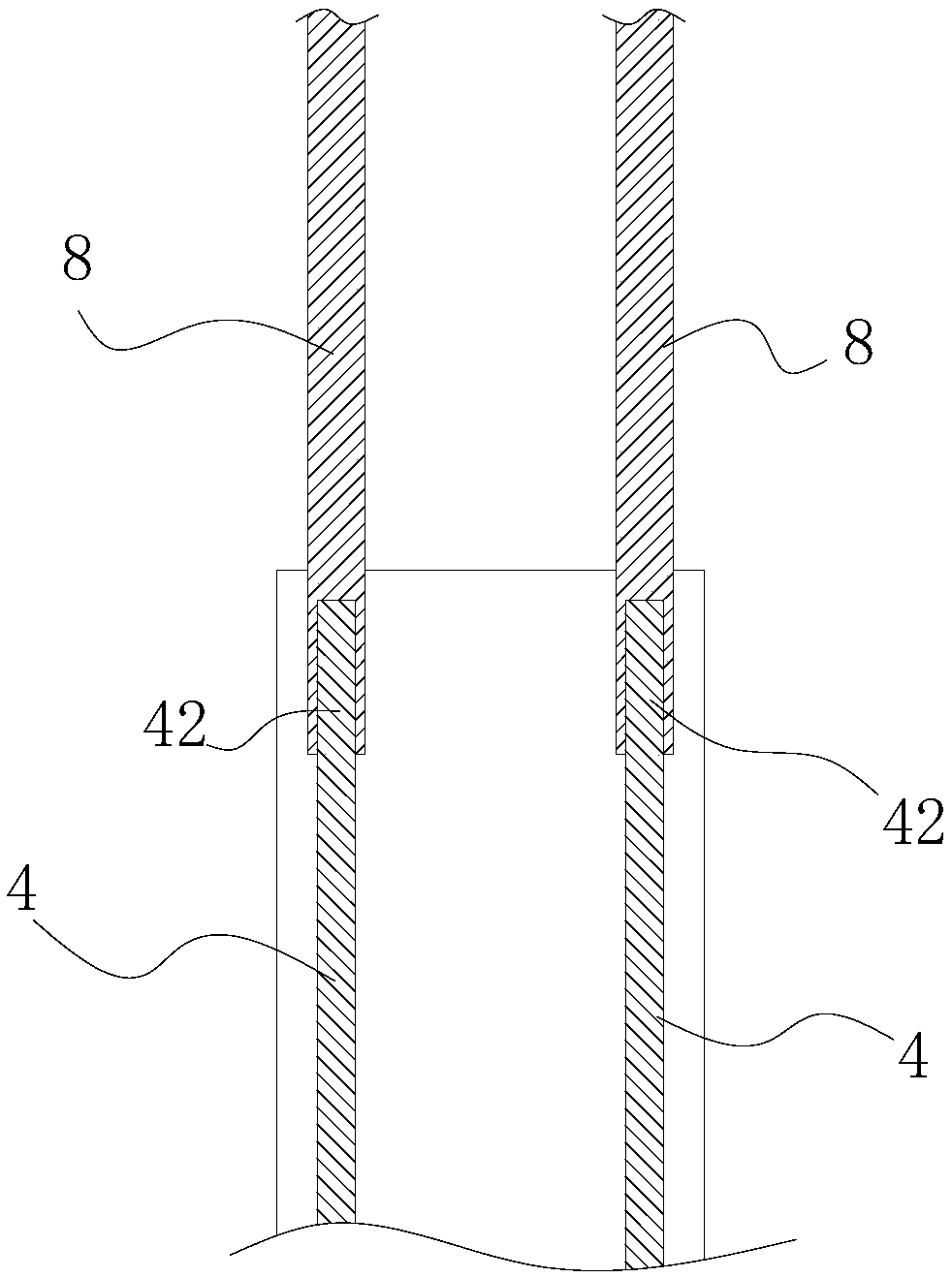
[0066] like Figure 1-4 As shown in Fig. 1, a single pile vertical pull-out static load test of the anchor connection method pull-out device, including the measured object and detection equipment. Wherein, the object to be tested is the test pile 2, which in this embodiment is specifically a cast-in-place pile, in which high-strength connectors are pre-embedded. The detection equipment includes buttresses 62 arranged on both sides of the test pile 2, a main beam 64 erected on the buttress 62 and suspended above the test pile 2, and a jack 66 arranged on the main beam 64, and the jack 66 is connected with a power device , Both sides of the test pile 2 are also provided with displacement detection structures, the output end of the jack 66 is connected to a number of pull rods 8 extending downward, and the test pile 2 is directly or indirectly anchored to the pull rods 8 through high-strength connectors.
[0067] Specifically, in this embodiment, the upper end of the jack 66, th...
Embodiment 2
[0076] like figure 1 , 4 As shown in -6, an anti-extraction device of an anchored connection method for a single pile vertical anti-extraction static load test is different from Embodiment 1 in that: the high-strength steel bar 4 is threadedly connected with the pull rod 8 through a sleeve 52.
[0077] Specifically, the pull rod 8 is also a high-strength connecting steel bar, and the outer surface is fully threaded. The casing 52 is provided with an internal thread so as to respectively screw the high-strength steel bar 4 and the anchor end of the tie rod 8 to connect the two. When pre-embedding, the high-strength steel bars 4 are also symmetrically bound on the concrete reinforcement cage. Note that the anchor ends 42 of the high-strength steel bars 4 are buried at a position 2 cm below the section of the pile top. The anchor ends 42 have a reserved length of 10-15 cm. Promptly need sleeve pipe 52 to be sleeved in the concrete pouring process of pile body, protect with plas...
Embodiment 3
[0080] like figure 1 , 7 As shown in -9, a single pile vertical pullout static load test of the anchor connection pullout device differs from Embodiment 1-2 in that the high-strength connector includes an anchor pull plate 54 arranged above the test pile 2, And some high-strength bolts 55 that are anchored to connect the anchor tie plate 54 and the test pile 2, and the upper end of the anchor tie plate 54 is anchored and connected with the pull rod 8.
[0081] This solution is especially suitable when the test pile 2 is a prestressed pipe pile and the anchor hole 24 is provided on the top end plate 21 of the pile body. Specifically, the number of high-strength bolts 55 in this embodiment is six, and preferably the positions of each high-strength bolt 55 are evenly distributed on the same circle B, and the positions of each tie rod 8 are also evenly distributed on the same circle C, and the circle where each tie rod 8 is located The projections of C and the circumference B wh...
PUM
 Abstract
Description
Claims
Application Information
 - R&D
- Intellectual Property
- Life Sciences
- Materials
- Tech Scout
- Unparalleled Data Quality
- Higher Quality Content
- 60% Fewer Hallucinations
Browse by: Latest US Patents, China's latest patents, Technical Efficacy Thesaurus, Application Domain, Technology Topic, Popular Technical Reports.
© 2025 PatSnap. All rights reserved.Legal|Privacy policy|Modern Slavery Act Transparency Statement|Sitemap|About US| Contact US: help@patsnap.com


