Oil-water separator for offshore wind farm

A technology of oil-water separator and wind farm, which is applied in the field of offshore wind power generation, can solve the problems of small amount of mixing, heavy weight, and high energy consumption, and achieve the effect of avoiding blockage

Pending Publication Date: 2018-09-04
POWERCHINA HUADONG ENG CORP LTD
View PDF8 Cites 2 Cited by
  • Summary
  • Abstract
  • Description
  • Claims
  • Application Information

AI Technical Summary

Problems solved by technology

[0004] The traditional technology is to set up accident oil tanks, such as the utility model patent No. ZL 201620150429.3 "An accident oil collection device for offshore booster stations", the accident oil tank has the function of oil-water separation and can store accident oil, but the traditional The accident fuel tank has the following disadvantages: (1) the accident fuel tank is full of water for a long time (more than 100t of water is stored), and it is heavy, which is unfavorable to the structural force; (2) for areas where the winter temperature is below zero, in order to prevent The oil-water separation function is lost due to the freezing of the accident oil tank. The periphery of the accident oil tank needs to be equipped with an insulation layer and electric heating equipment, which requires a large amount of heat preservation work and high energy consumption; (3) After only one oil-water separation, a small amount of oil droplets may be mixed into the water outlet

Method used


Image

  • Oil-water separator for offshore wind farm
  • Oil-water separator for offshore wind farm
  • Oil-water separator for offshore wind farm

Examples


Embodiment Construction

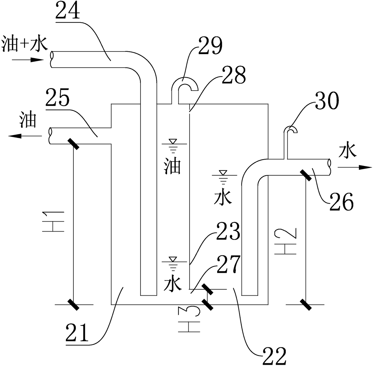
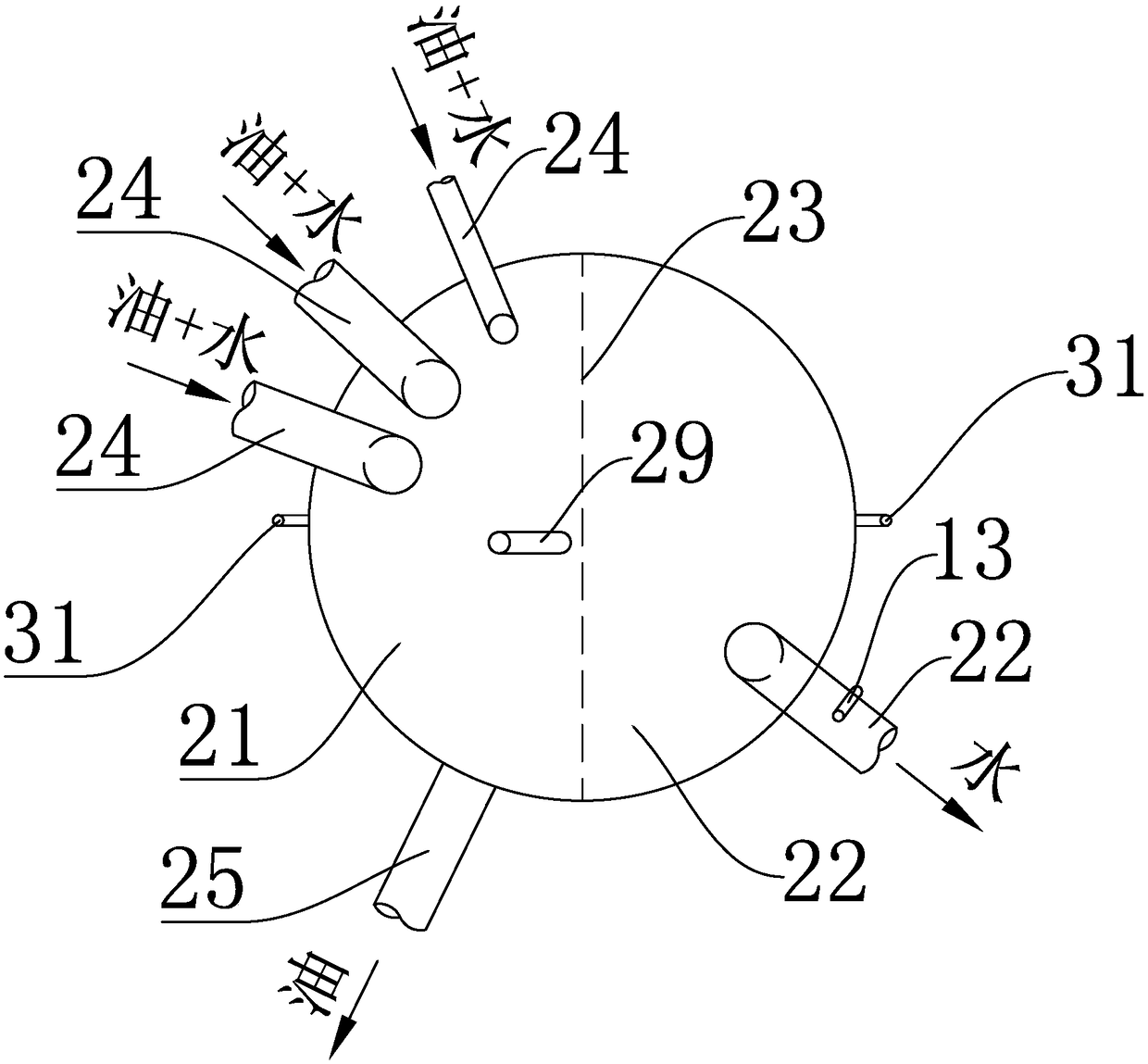
[0026] Such as figure 1 , figure 2 and image 3 As shown, this embodiment is an oil-water separator used in offshore wind farms, which has an oil-water separator 2, which is installed between the main transformer accident oil sump 1 and the emergency oil storage tank 3, and is used to convert the secondary The oil-water mixture discharged from the main transformer accident oil sump 1 is separated, the oil is collected in the accident oil storage tank 3, and the water is discharged. In areas where the water in the oil-water separator 2 can freeze when the lowest temperature is lower than 0°C in winter, it is necessary to install an insulation layer on the outer wall of the oil-water separator 2. Prevent the water in the oil-water separator 2 from freezing in cold regions or in winter, and lose the oil-water separation function.

[0027] In this embodiment, the oil-water separator 2 is a cylindrical structure with a diameter of 1.5 m and a total height of 30 m. The cylinder ...


PUM


Abstract

The invention relates to an oil-water separator for an offshore wind farm. The invention aims at providing the oil-water separator with simple structure and reliable function for the offshore wind farm; the oil-water separator can quickly separate an oil-water mixture into oil and water, also has the function of a water sealing box, and can isolate the spread of combustion gas to and prevent firefrom expanding. The technical scheme of the invention is that the oil-water separator for the offshore wind farm is characterized in that: the oil-water separator is arranged; the oil-water separatoris divided into an oil storage compartment and a water storage compartment via a partition plate; a water draining hole is formed in the bottom of the partition plate; an air vent hole is formed in the upper part of the partition plate; the top of the oil storage compartment is connected with a plurality of oil inlet pipes leading to the bottom of the oil storage compartment; an oil draining pipeis arranged on the upper part of a side wall of the oil storage compartment; and a water draining pipe is arranged on the upper part of the side wall of the water storage compartment. The oil-water separator is applicable to the field of offshore wind power generation.

Description

technical field [0001] The invention relates to an oil-water separator used in an offshore wind farm, which is suitable for the field of offshore wind power generation. Background technique [0002] With the rapid development of my country's wind power industry, offshore wind power has started rapidly. In recent years, a large number of offshore wind farms under construction or proposed have emerged. The offshore booster station or offshore converter station is an essential part of the offshore wind farm as an auxiliary power output facility for the offshore wind farm. [0003] The oil-containing equipment in the offshore booster station or offshore converter station is generally the main transformer, diesel engine, diesel oil storage tank, etc. These equipment will not leak oil under normal conditions, but they will actively drain or leak oil in case of fire or other accidents. In the event of a fire in the main transformer, in order to protect the main transformer body an...

Claims


Application Information

Patent Timeline
Patent Type & Authority Applications(China)
IPC IPC(8): C02F1/40
CPCC02F1/40C02F2103/007F03D80/00F03D13/25F05B2240/96B01D17/0211B01D17/0214B01D17/12Y02E10/727Y02E10/72F03D80/70F05B2240/95F05B2260/98
Inventor 俞华锋戚海峰黄春林赵生校汤群益张震洲张栋梁袁建平贾献林楼巍张宝峰
Owner POWERCHINA HUADONG ENG CORP LTD
Why Eureka
Try Eureka