A seamless track rail displacement crawling detection system
A seamless track rail and detection system technology, which is applied in the direction of railway vehicle shape measuring devices, railway car body parts, railway auxiliary equipment, etc., can solve the difficulties in maintenance of displacement observation piles, low accuracy of measurement data, and difficult maintenance, etc. problems, to achieve the effect of eliminating personnel safety risks, facilitating data query, and ensuring operational safety
- Summary
- Abstract
- Description
- Claims
- Application Information
AI Technical Summary
Problems solved by technology
Method used
Image
Examples
Embodiment 1
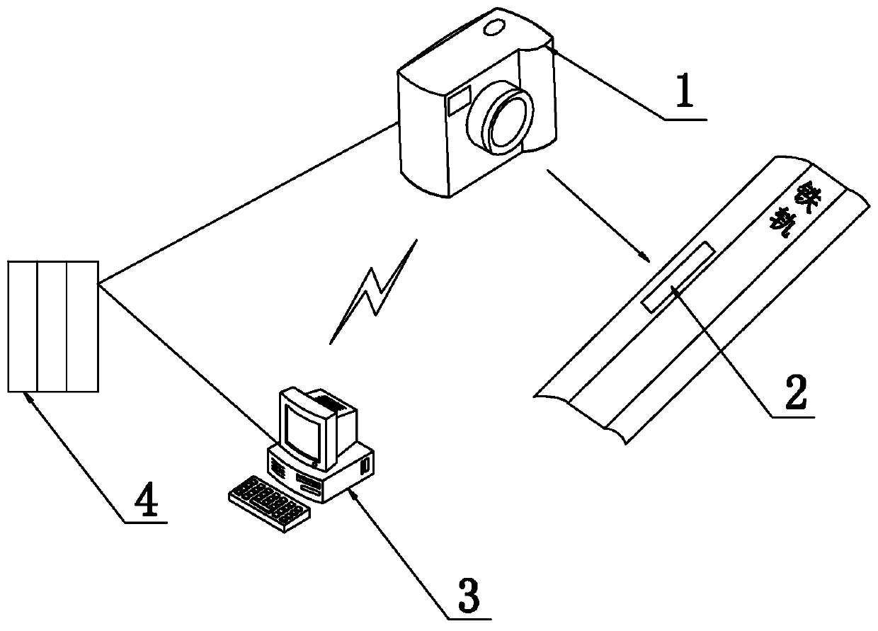
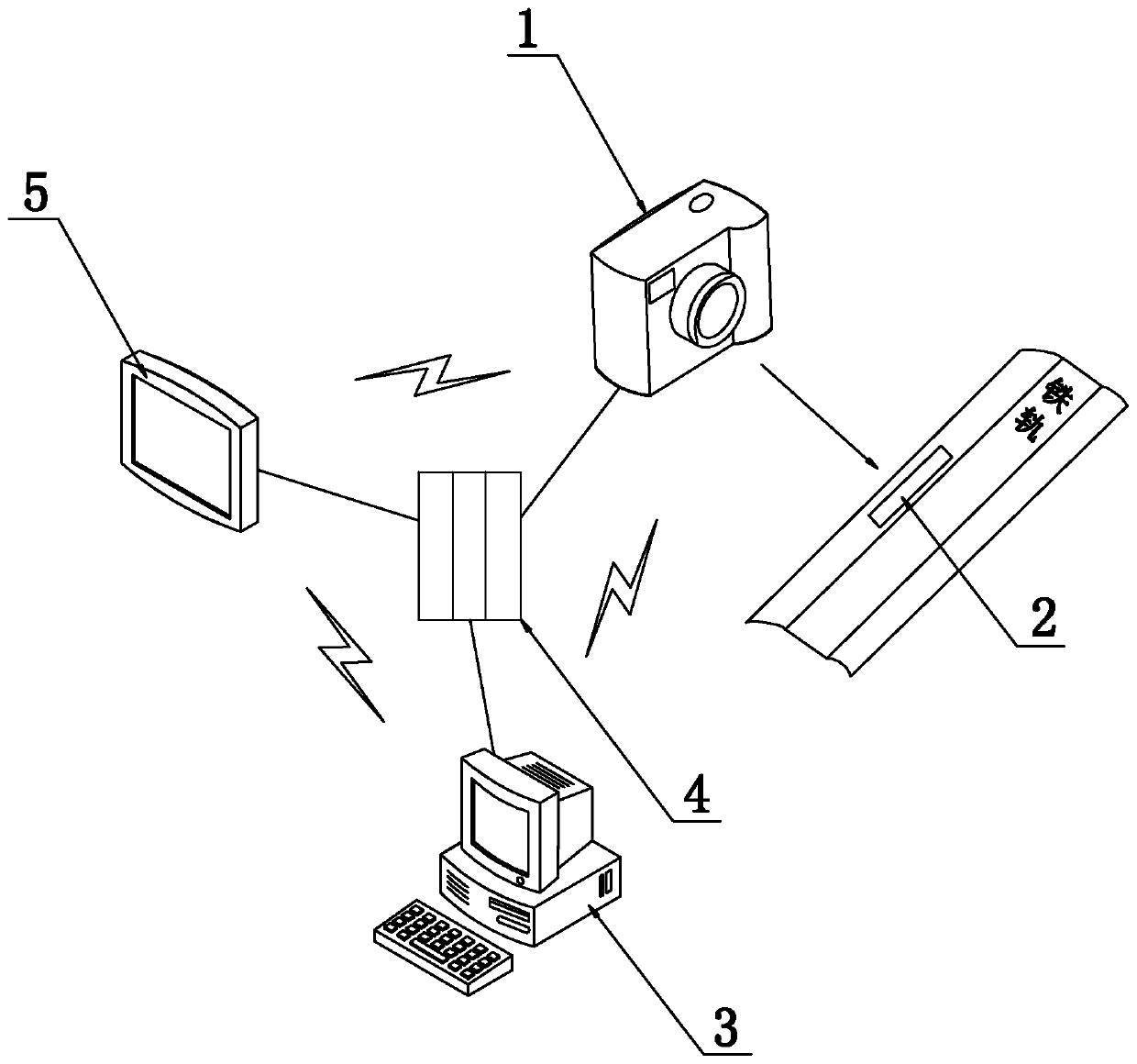
[0047] Embodiment 1 of the present invention provides a rail displacement crawling detection system for seamless lines. The system can measure rail displacement in real time with accurate measurement, and can record and store data in time. Specifically, as figure 1 As shown, the system includes on-site basic equipment, a main control operating system 3 and a power supply system 4. The on-site basic equipment includes an image acquisition system 1 installed on catenary poles along the railway line and a scale scale 2 set on the rail waist. The acquisition system 1 is parallel to the installation position of the scale scale 2, the on-site basic equipment is installed on the rail displacement measurement site, the main control operating system 3 is set in the background, such as the upper computer, and the power supply system 4 is used to provide electric energy for the on-site equipment and the background equipment. use, where,
[0048] The image acquisition system 1 is responsi...
Embodiment 2
[0054] Embodiment 2 of the present invention further defines a seamless track rail displacement crawling detection system on the basis of Embodiment 1, specifically:
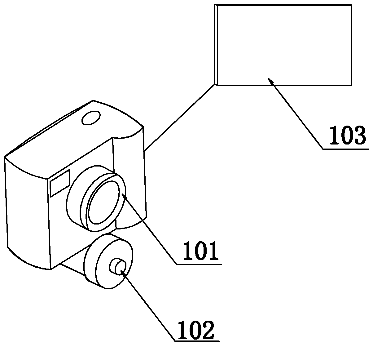
[0055] Such as figure 2 As shown, the image acquisition system 1 includes a camera device 101, a laser head 102 positioned vertically below the camera device 101 and a high-definition video acquisition card 103 connected to the camera device 101, and the laser head 102 is used to emit laser marks irradiated on the scale scale 2 , the imaging device 101 is used for real-time shooting of the displacement image irradiated by the laser mark on the scale scale 2, and the high-definition video acquisition card 103 is used for storing the displacement image in real time and sending it to the main control operating system 3. The imaging device 101 is a zoom camera, The camera can still operate normally in an outdoor environment of -40°C. The imaging device 101 is provided with a far and near zoom button and a far and ...
Embodiment 3
[0066] Embodiment 3 of the present invention further defines the structure of the main control operating system 3 on the basis of Embodiment 2, and improves the intelligent operation of the system.
[0067] Such as Figure 5 As shown, the main control operating system 3 includes a connected central processing unit 31 and a database 32, the central processing unit 31 is connected with the touch port of the touch display screen through a USB2. Connection, the operation buttons include page up, page down, screen saver and recording, the central processing unit 31 is connected with the high-definition video capture card 103 through the USB3. The zoom button and the far-near focus button adjust the imaging device 101 . The main control operating system 3 can be a 2.5-inch Advantech industrial control computer, customized embedded win7 system, the central processing unit 31 is a 1.9GHZ CPU, and the database 32 includes 8G memory and 40G hard disk, which can store a large amount of ...
PUM
 Abstract
Description
Claims
Application Information
 - R&D
- Intellectual Property
- Life Sciences
- Materials
- Tech Scout
- Unparalleled Data Quality
- Higher Quality Content
- 60% Fewer Hallucinations
Browse by: Latest US Patents, China's latest patents, Technical Efficacy Thesaurus, Application Domain, Technology Topic, Popular Technical Reports.
© 2025 PatSnap. All rights reserved.Legal|Privacy policy|Modern Slavery Act Transparency Statement|Sitemap|About US| Contact US: help@patsnap.com


