Self-preheating temperature adjusting gas burner
A gas burner, self-preheating technology, applied in the direction of burner, combustion method, combustion type, etc., can solve the problem of uncontrollable heating temperature of gas burner, achieve the effect of increasing temperature, saving energy, and good combustion effect
- Summary
- Abstract
- Description
- Claims
- Application Information
AI Technical Summary
Problems solved by technology
Method used
Image
Examples
Embodiment 1
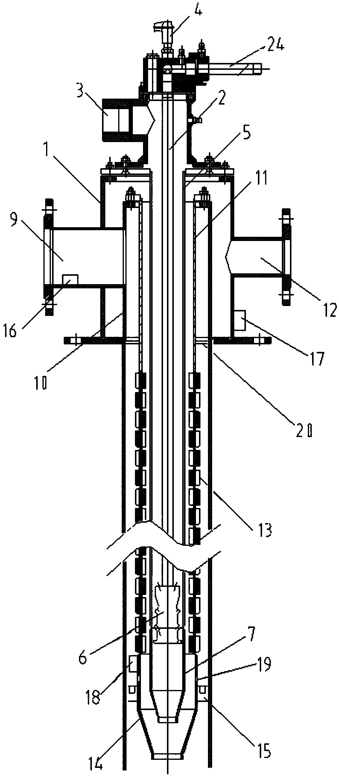
[0032] Such as figure 1 As shown, the present invention provides a self-preheating and temperature-regulating gas burner, including: a housing 1;
[0033] The gas pipe 2 is located inside the casing 1 and arranged along the axis of the casing 1, and both ends of the gas pipe 2 protrude from both ends of the casing 1;
[0034] A primary air guide tube 5 is arranged inside the housing 1, and the primary air guide tube 5 is coaxially sleeved on the outside of the gas pipe 2. The tuyere 3 is arranged on the casing 1, and the end of the primary air guide pipe 5 away from the casing 1 communicates with the gas outlet end of the gas pipe 2;
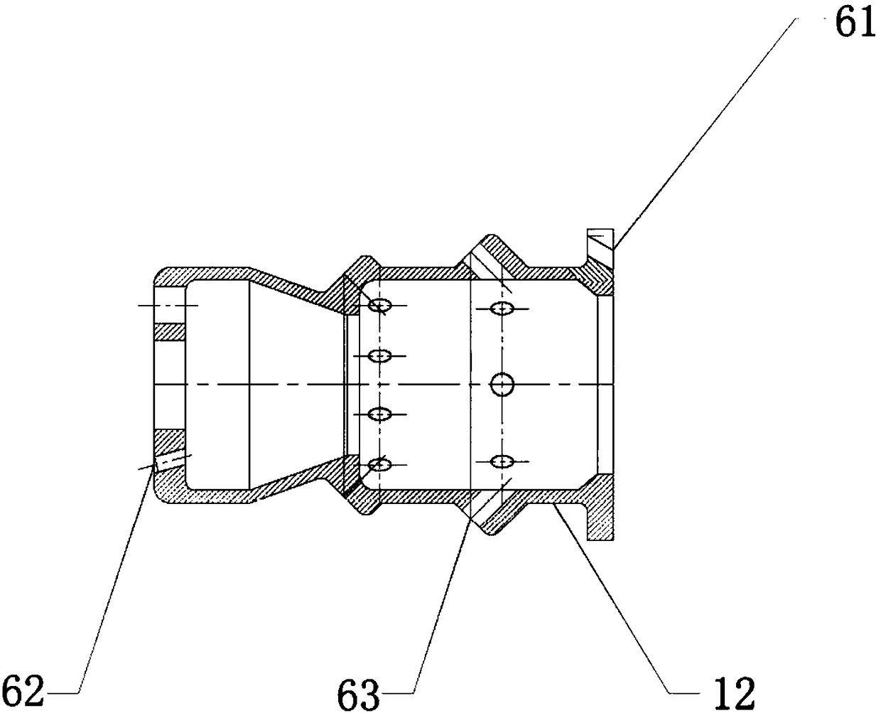
[0035] A smoke guide pipe 10 is arranged inside the shell 1, and the smoke guide pipe 10 is coaxially sleeved on the outside of the primary air guide pipe 5, and a secondary air guide pipe 11 is coaxially arranged inside the smoke guide pipe 10, and the secondary air guide pipe 11 The secondary air guide pipe 11 communicates with the gas outle...
Embodiment 2
[0047] Such as image 3 As shown, on the basis of Embodiment 1, in order to prevent insufficient combustion of gas, a combustible gas detector 16 is set at the smoke discharge port 9, and a controller 17 is set on the housing 1, and the controller 17 is connected to an external power source, and the combustible gas The detector 16 is connected with the controller 17; the second igniter 18 is arranged on the outside of the first closed pipe 14, and the second igniter 18 is connected with the controller 17; the side of the first closed pipe 14 offers several side holes 19, and the side holes 19 are located at Between the second igniter 18 and the mouth end of the first closing pipe 14; when the combustible gas detector 16 detects combustible gas, the controller 17 controls the second igniter 18 to ignite, and the side hole 19 provides fuel for insufficiently combusted gas. Oxygen, an anti-backfire valve 20 is set between the flange plate 8 and the primary air guide pipe 5, so th...
Embodiment 3
[0049] Such as Figure 4 As shown, on the basis of Embodiment 1, an annular groove 21 is provided at one end of the heat exchange tube 13 close to the housing 1, the outer surface of the annular groove 21 is connected to the flange 8, and the inner surface of the annular groove 21 is connected to the flange 8. The gap is set, the notch of the annular groove 21 faces the housing 1, and the end of the secondary air guide tube protruding from the housing 1 is provided with a second closing tube 22, and the small opening of the second closing tube 22 is sealed and connected with the secondary air guiding tube , the small opening of the second closing pipe 22 is set towards the housing 1, the large mouth end of the second closing pipe 22 is inserted into the annular groove 21, and has a gap with the annular groove 21, and a plurality of smoke check valves 23 are arranged at the bottom of the annular groove 21, The flue gas check valve 23 is located between the outer wall of the ann...
PUM
 Abstract
Description
Claims
Application Information
 - R&D
- Intellectual Property
- Life Sciences
- Materials
- Tech Scout
- Unparalleled Data Quality
- Higher Quality Content
- 60% Fewer Hallucinations
Browse by: Latest US Patents, China's latest patents, Technical Efficacy Thesaurus, Application Domain, Technology Topic, Popular Technical Reports.
© 2025 PatSnap. All rights reserved.Legal|Privacy policy|Modern Slavery Act Transparency Statement|Sitemap|About US| Contact US: help@patsnap.com


