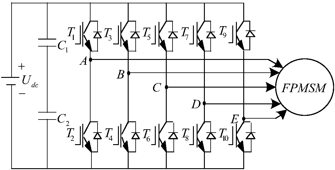
Detection method for detecting open-circuit fault of five-phase permanent magnet synchronous motor inverter

A permanent magnet synchronous motor, open-circuit fault technology, applied in the direction of measuring electrical variables, instruments, measuring electricity, etc., to achieve the effect of saving costs and increasing speed

Active Publication Date: 2018-08-24
JIANGSU UNIV
View PDF4 Cites 2 Cited by
  • Summary
  • Abstract
  • Description
  • Claims
  • Application Information

AI Technical Summary

Problems solved by technology

[0027] The purpose of the present invention is to solve the problems existing in the above-mentioned existing current-based inverter open-circuit fault detection method, and to provide a detection method for five-phase permanent magnet synchronous motor inverter open-circuit fault, which can be realized without complex coordinate transformation Accurately locate the open-circuit fault types of single-tube fault, single-phase fault, adjacent two-phase fault and non-adjacent two-phase fault in the inverter

Method used


Image

  • Detection method for detecting open-circuit fault of five-phase permanent magnet synchronous motor inverter
  • Detection method for detecting open-circuit fault of five-phase permanent magnet synchronous motor inverter
  • Detection method for detecting open-circuit fault of five-phase permanent magnet synchronous motor inverter

Examples


Embodiment 1

[0079] see Figure 4 ~ Figure 9 is the current waveform and the detection variable d after four types of faults occur in the motor n waveform.

[0080] The parameters of the five-phase permanent magnet synchronous motor in this embodiment are shown in Table 1:

[0081] Table 1 Parameters of five-phase permanent magnet synchronous motor

[0082]

[0083] The given rotational speed is 500rpm and the torque is 12Nm. Detection threshold k 1 =-1,k 2 =0.2,k 3 = 2.5.

[0084] Figure 4 is the current waveform of the motor after a single-tube, single-phase open-circuit fault occurs, Figure 5 is the detection variable d after the motor has a single-tube, single-phase open-circuit fault n The waveform:

[0085] When the motor is in 0.18~0.2s, d n About 1, fault indication D n =N, According to the fault indication signal, it is found that there is no open circuit fault, that is, the motor is running normally;

[0086] The motor can detect d after a period of time after 0...

Embodiment 2

[0096] Figure 10-11 After the motor speed changes, the current waveform and the detected variable d n waveform.

[0097] In this embodiment, the given five-phase permanent magnet synchronous motor torque is 12Nm. From 0 to 0.5s, the given speed is 700rpm. After 0.5s, the speed suddenly changes to 500rmp, and after 0.7s, the speed changes to 600rpm. The current waveform during the whole speed change process is as follows: Figure 10 shown. From Figure 11 It can be seen that although the detection variable has a small change in the process of the speed change, it does not affect the detection result, and after the speed is stable, the detection variable also returns to around 1, which shows that the change of the speed will not affect the fault detection. Results make a difference.

Embodiment 3

[0099] Figures 12 to 13 After the motor torque changes, the current waveform and the detected variable d n waveform.

[0100] In this embodiment, the given five-phase permanent magnet synchronous motor rotates at a speed of 500 rpm. The given torque is 3Nm from 0 to 0.5s, the torque suddenly changes to 12Nm after 0.5s, and the torque changes to 6Nm after 0.7s. The current waveform during the whole torque change process is as follows: Figure 12 shown. From Figure 13 It can be seen that although the detection variable has a small change during the torque change process, it does not affect the detection result, and after the torque is stable, the detection variable also returns to around 1, which shows that the torque change will not affect the fault detection results.


PUM


Abstract

The invention discloses a detection method for detecting the open-circuit fault of a five-phase permanent magnet synchronous motor inverter. According to the method, the fault detection variables of all phases are calculated according to the periodic average value and the absolute average value of five-phase currents. The fault detection variables are compared with a preset threshold value and then the fault indication signal of the inverter is obtained. According to the fault indication signal, the fault detection and the fault positioning are carried out. In this way, the type of the open-circuit fault of the inverter is determined. As a result, the four types of the inverter, namely the single-tube fault, the single-phase fault, the adjacent two-phase fault and the non-adjacent two-phase fault of the inverter, can be accurately positioned. The rapid detection and the rapid positioning of the open-circuit fault of the five-phase inverter are realized. The complex coordinate transformation and additional hardware circuits are not needed, and the fault detection speed is increased.

Description

technical field [0001] The invention relates to the field of open-circuit fault detection of motor inverters, in particular to a detection method for open-circuit faults of inverters of five-phase permanent magnet synchronous motors. Background technique [0002] The multi-phase motor drive system realizes low-voltage high-power transmission by increasing the number of phases of the stator winding. Compared with the traditional three-phase motor drive system, the amplitude of the output torque ripple is reduced, which reduces the vibration and noise of the motor; The power capacity of each phase of the bridge arm of the transformer is small, which avoids the problems of dynamic and static voltage equalization and current equalization caused by the series and parallel connection of switching devices; the redundancy of the number of phases enables it to continue fault-tolerant operation under fault conditions, improving the System reliability. [0003] Generally, a motor driv...

Claims


Application Information

Patent Timeline
Patent Type & Authority Applications(China)
IPC IPC(8): G01R31/02
CPCG01R31/50
Inventor 全力赵美玲朱孝勇
Owner JIANGSU UNIV
Why Eureka
Try Eureka