Injection molding machine

A technology for injection molding machines and tube heads, which is applied in the field of injection molding equipment, can solve the problems of long maintenance time and reduced processing efficiency of injection molding machine nozzles, and achieve the effects of shortening maintenance and replacement time, short replacement time and high production efficiency

Active Publication Date: 2018-08-24
宁波鑫神泽汽车零部件有限公司
View PDF5 Cites 1 Cited by
  • Summary
  • Abstract
  • Description
  • Claims
  • Application Information

AI Technical Summary

Problems solved by technology

[0004] The object of the present invention is to provide an injection molding machine to solve the problem of reduced processing efficiency caused by long maintenance time after the nozzle of the injection molding machine is blocked

Method used


Image

  • Injection molding machine
  • Injection molding machine
  • Injection molding machine

Examples


Embodiment Construction

[0019] The present invention will be described in further detail below by means of specific embodiments:

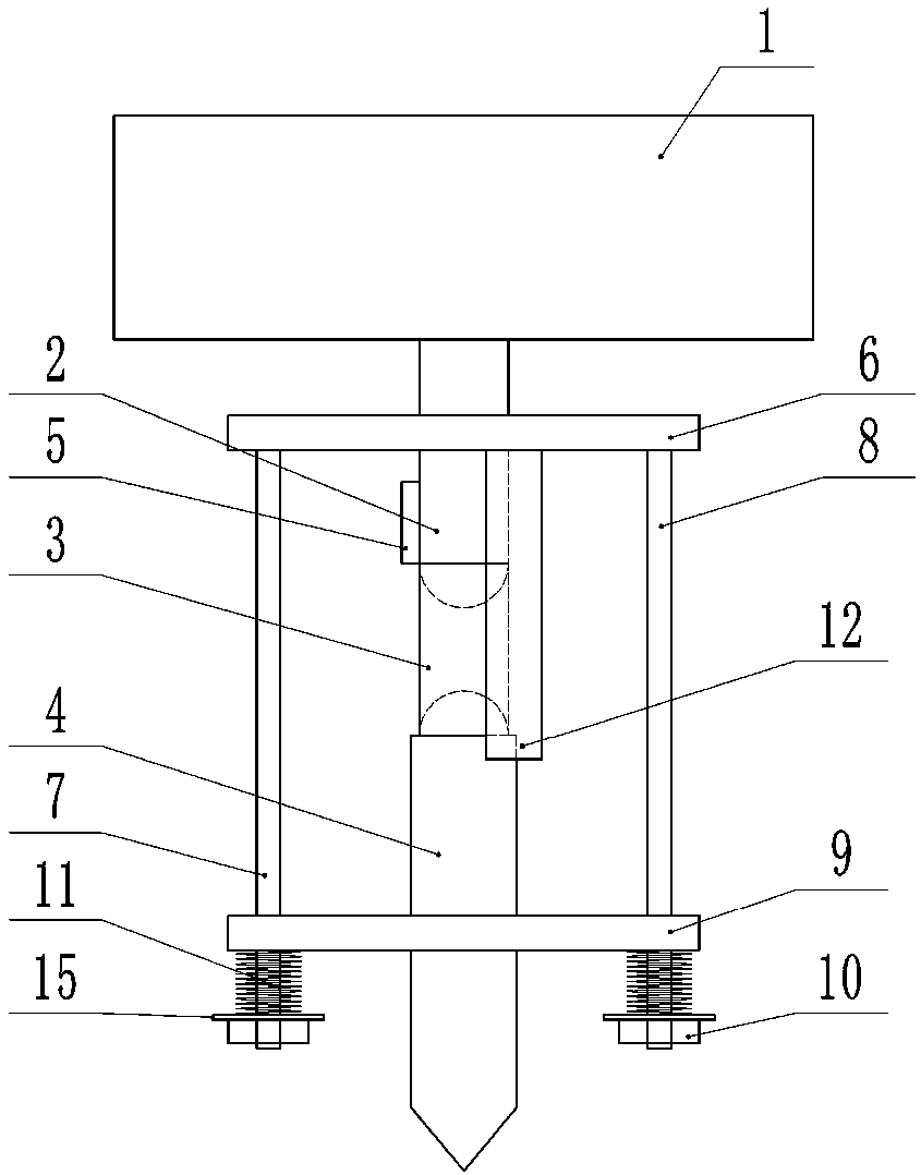
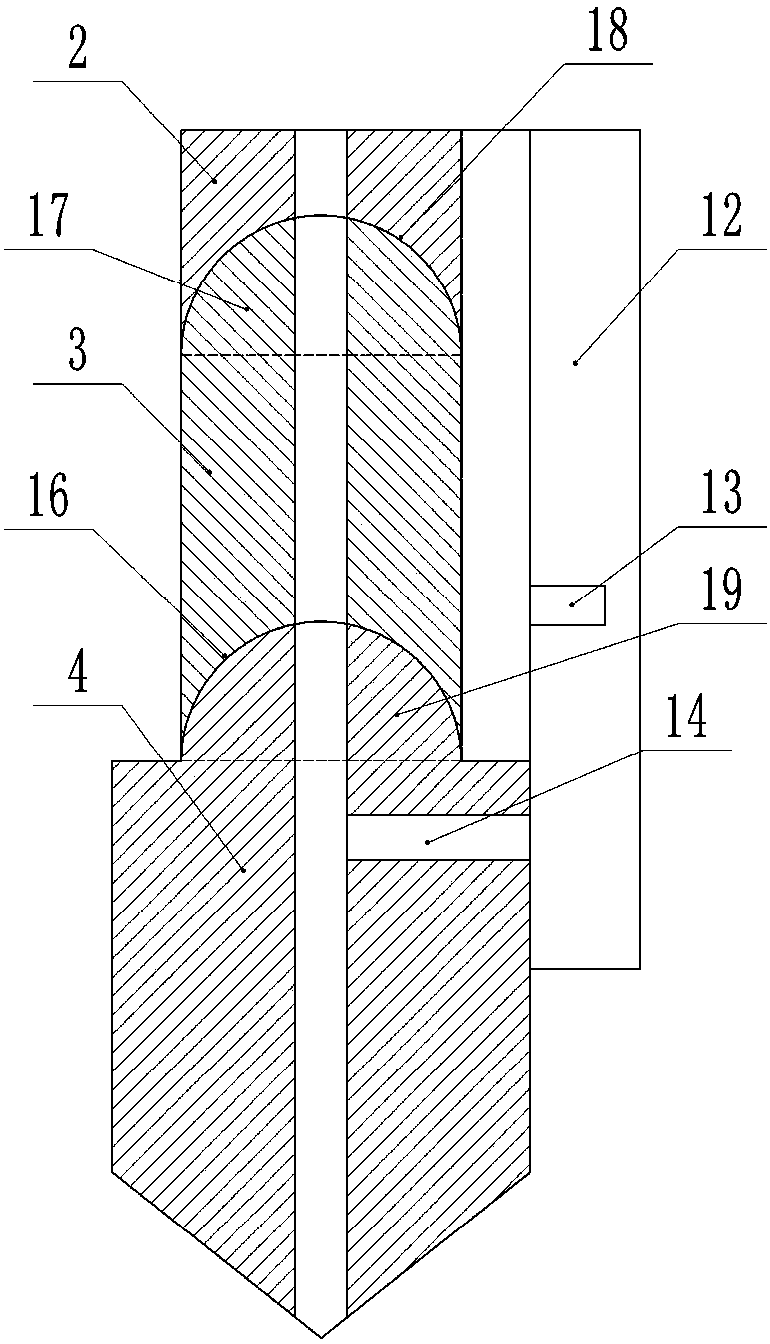
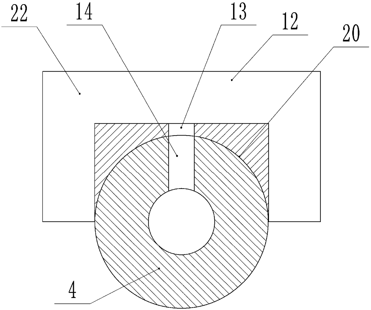
[0020] The reference signs in the accompanying drawings of the description include: storage tank 1, first pipe head 2, second pipe head 3, third pipe head 4, rubber sleeve 5, first horizontal plate 6, first vertical bar 7, first Two vertical rods 8, second horizontal plate 9, nut 10, first spring 11, fixed plate 12, first through hole 13, third through hole 14, gasket 15, first groove 16, first protrusion 17 , the second groove 18 , the second protrusion 19 , the third groove 20 , the baffle plate 21 , and the cavity structure 22 .

[0021] Such as figure 1 As shown, an injection molding machine includes a material storage box 1, the lower part of the material storage box 1 is connected with a first pipe head 2, a second pipe head 3 and a third pipe head 4 in sequence, and the upper end of the second pipe head 3 is processed with The first semicircular protrusion 17, th...


PUM


Abstract

The application belongs to the technical field of injection molding equipment and particularly discloses an injection molding machine. The injection molding machine comprises a materiel storage box and a spray nozzle communicating with the materiel storage box is arranged on the materiel storage box; the spray nozzle comprises a first pipe head, a second pipe head and a third pipe head, wherein the first pipe head, the second pipe head and the third pipe head communicate in sequence; a rubber sleeve connected with the first pipe head in a sealing and sleeving manner is arranged on the second pipe head; a first transverse plate is arranged on the first pipe head, a first vertical rod is arranged at one side of the first transverse plate and a second vertical rod is arranged at the other side of the first transverse plate; the third pipe head is fixedly connected with a second transverse plate and the second transverse plate is connected with the first vertical rod and the second vertical rod by nuts; first springs are connected between the nuts and the second transverse plate and a fixing plate is arranged on the first transverse plate. The injection molding machine is mainly used for injection molding and the problem is solved that the inspection time after the spray nozzle of the injection molding machine is blocked is long and therefore the machining efficiency is lowered.

Description

technical field [0001] The invention belongs to the technical field of injection molding equipment, and specifically discloses an injection molding machine. Background technique [0002] Injection molding is a method of producing shapes for industrial products. Products usually use rubber injection molding and plastic injection molding. Injection molding can also be divided into injection molding molding method and die casting method. Injection molding is usually done by an injection molding machine, which is the main molding equipment for making thermoplastic or thermosetting materials into plastic products of various shapes using plastic molding molds. Injection molding is realized by injection molding machines and molds. [0003] During the injection molding process of the injection molding machine, due to the impurities contained in the injection molding raw materials, the nozzle of the injection molding machine is prone to clogging. After the nozzle is blocked, it nee...

Claims


Application Information

Patent Timeline
Patent Type & Authority Applications(China)
IPC IPC(8): B29C45/17B29C45/20
CPCB29C45/1753B29C45/20
Inventor 王健
Owner 宁波鑫神泽汽车零部件有限公司
Why Eureka
Try Eureka